
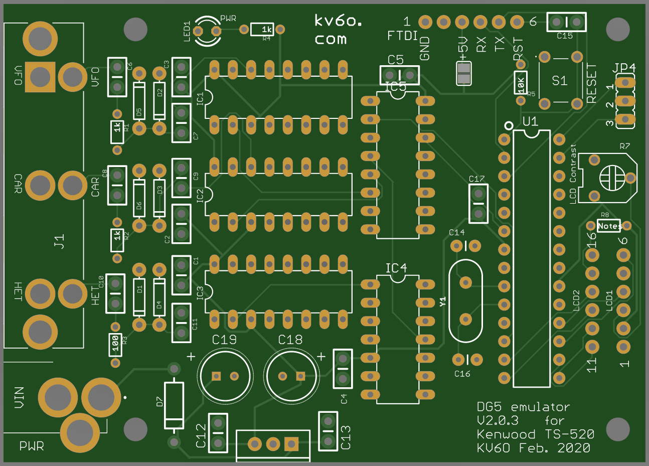
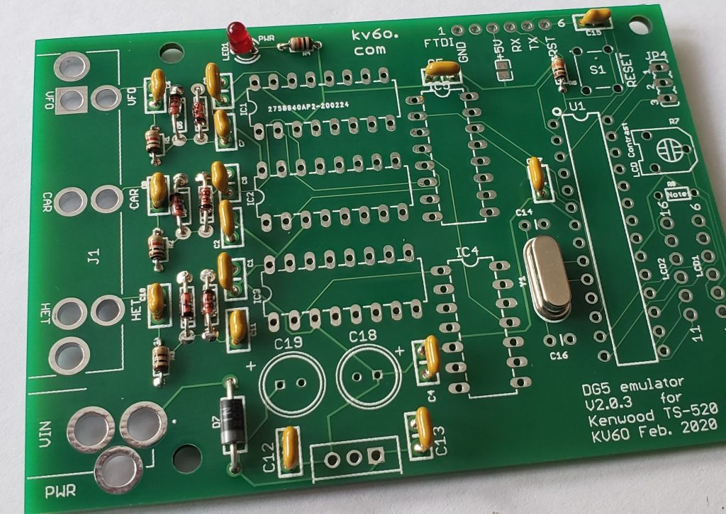
The DG5 V2.0.3 PCB is the self contained DG5 emulator – not a shield. The Atmel 328P and other supporting hardware are all on a single PCB.
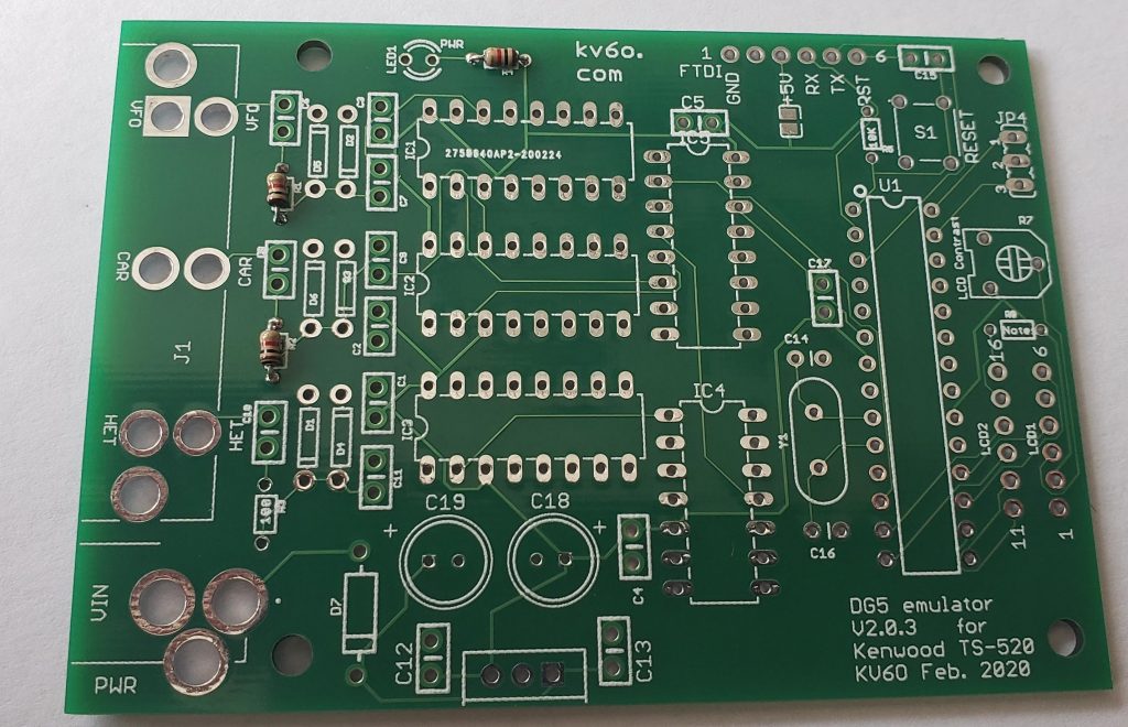
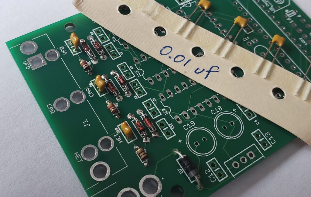
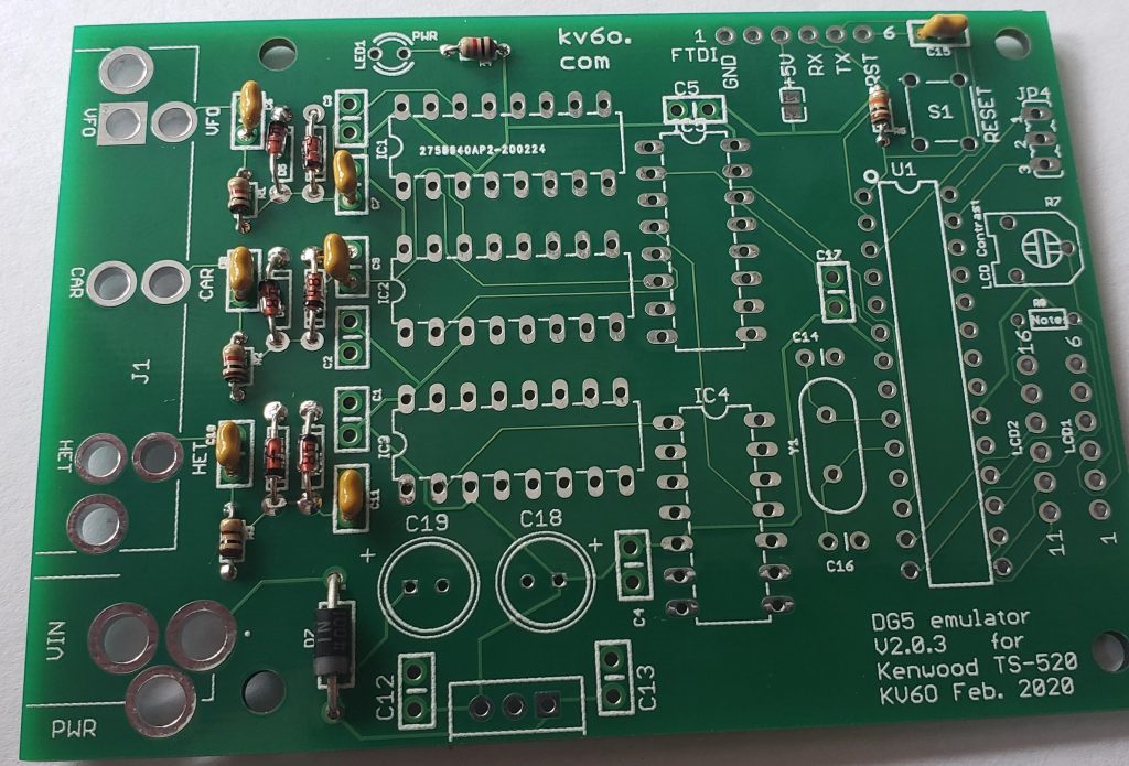
To build it, it’s best to start with the smallest parts first, which are the 1/8W resistors and diodes. The silkscreen on the actual PCB is a little difficult to read, so the above picture can be used as a reference. First, it’s best to get everything laid out and check your parts against the Bill of Materials (BOM).
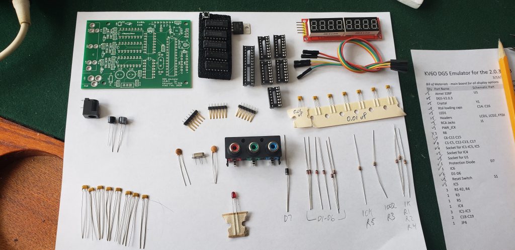
The 8 loose caps (lower left in pic above) are the 0.1uF used for power supply filtering and bypass caps for the IC’s. The 7 caps in a paper holder (in this case) are the 0.01uF signal coupling caps. These caps, along with the resistors and diodes are the smallest parts, so it’s easiest to solder them in first.
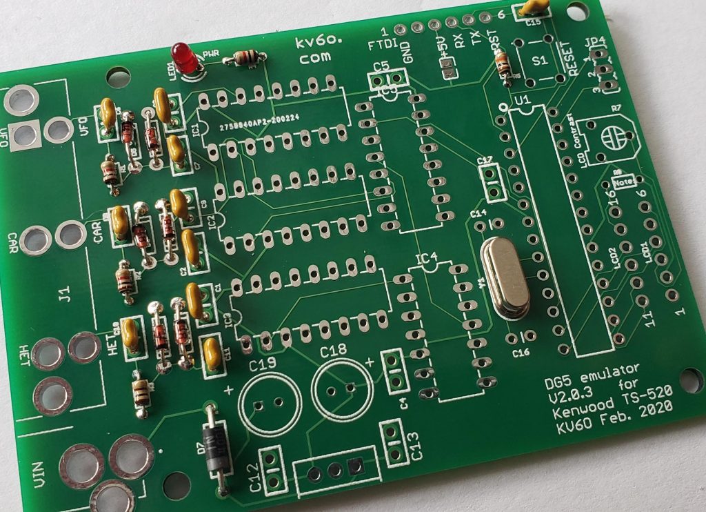
Pic above is with the 3, 1k resistors installed.
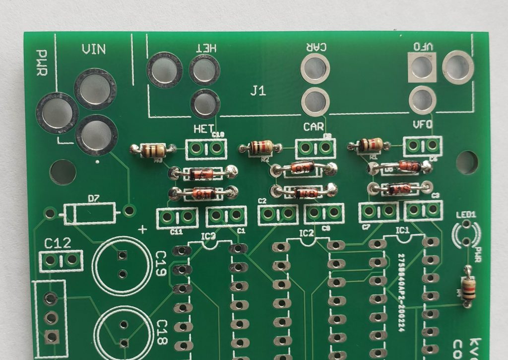
Pic above with R3 (100 ohm) and D1-D6 diodes in the signal conditioning section installed.
C6, C8, and C10 (0.01uF) have been installed
Added C7, C9, C11, C15 (0.01uF), D7 (1N4001), and R5 (10k)
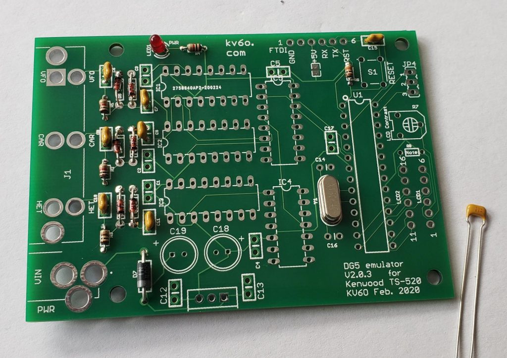
Added LED (Long leg towards resistor) and 16Mhz crystal (Y1). 0.1uF cap to the right is ready to be installed!
C1-C3 installed.
The rest of the bypass caps installed along with supply filters – C4-C5, C12-C13, and C17
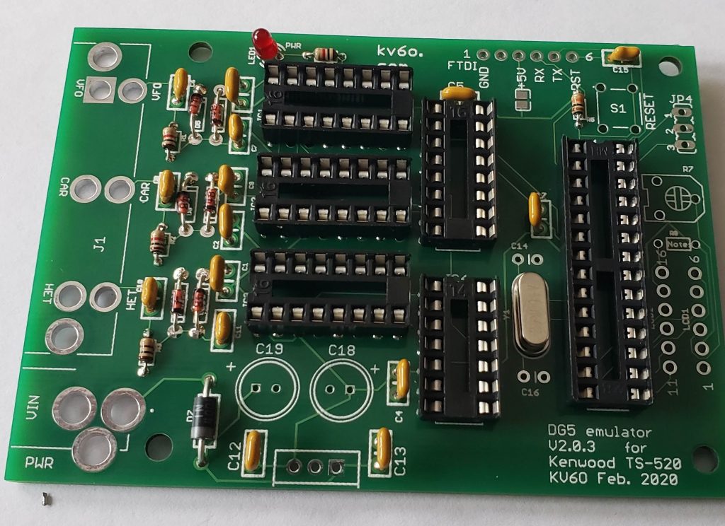
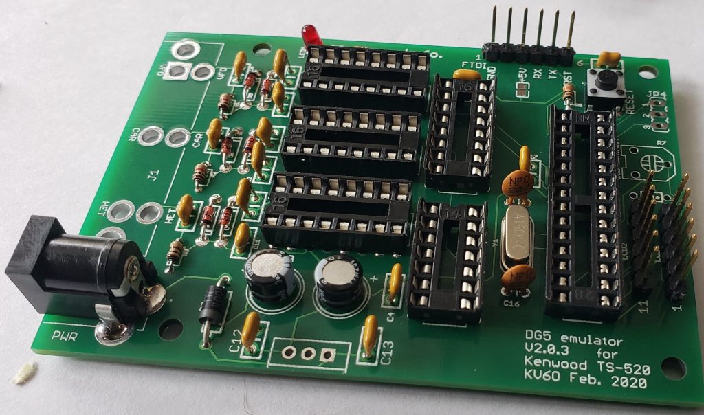
Next, install all the DIP sockets. There are 4, 16pin sockets, 1 14-pin, and 1 28-pin socket.
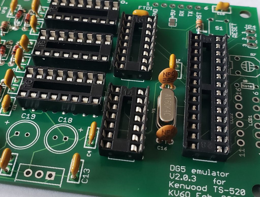
Add the 2, 22pF crystal loading caps. They might look different as these are what I had on hand.
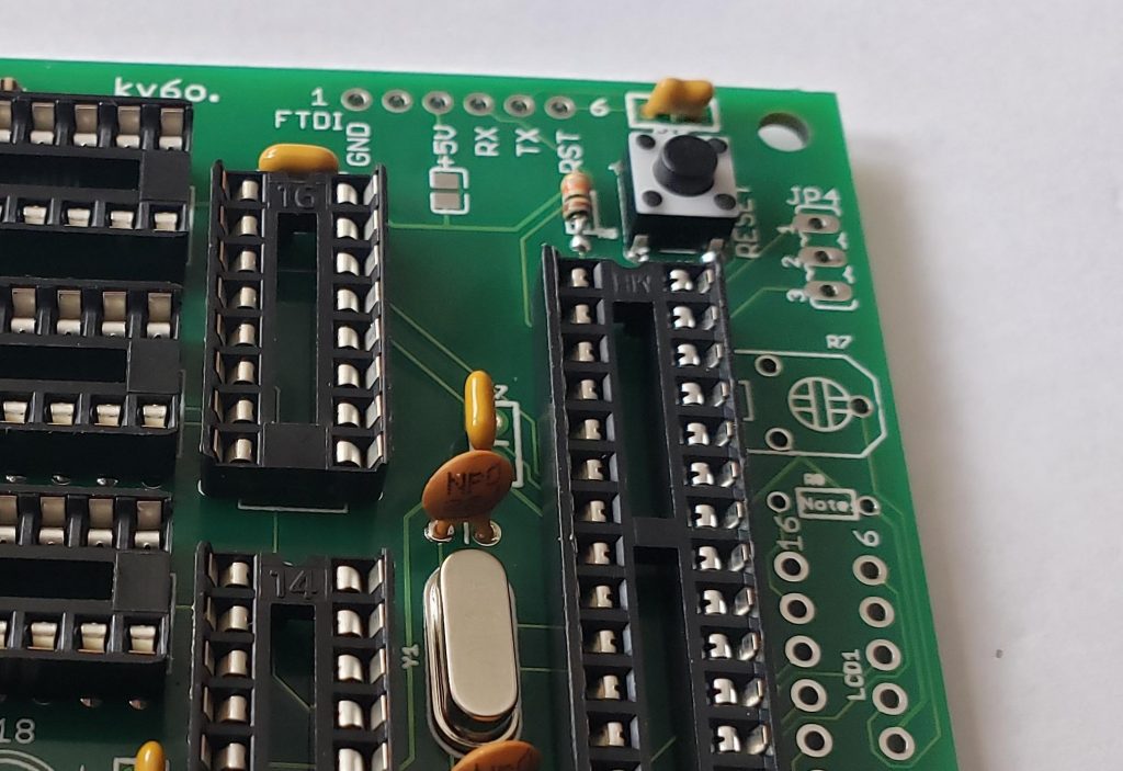
Add the reset switch. This is to reset the Atmel 328P if necessary.
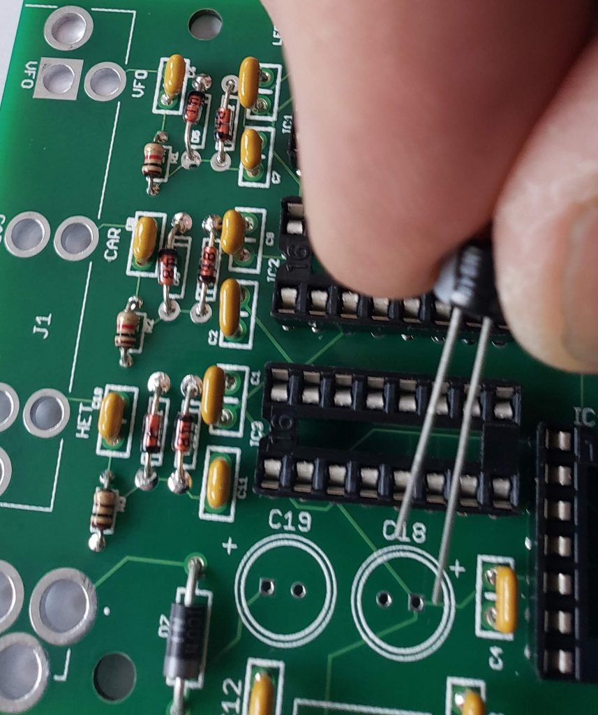
Add C18 and C19 – both polarized, 47uF caps. Note the polarity when installing – the longer lead is positive.
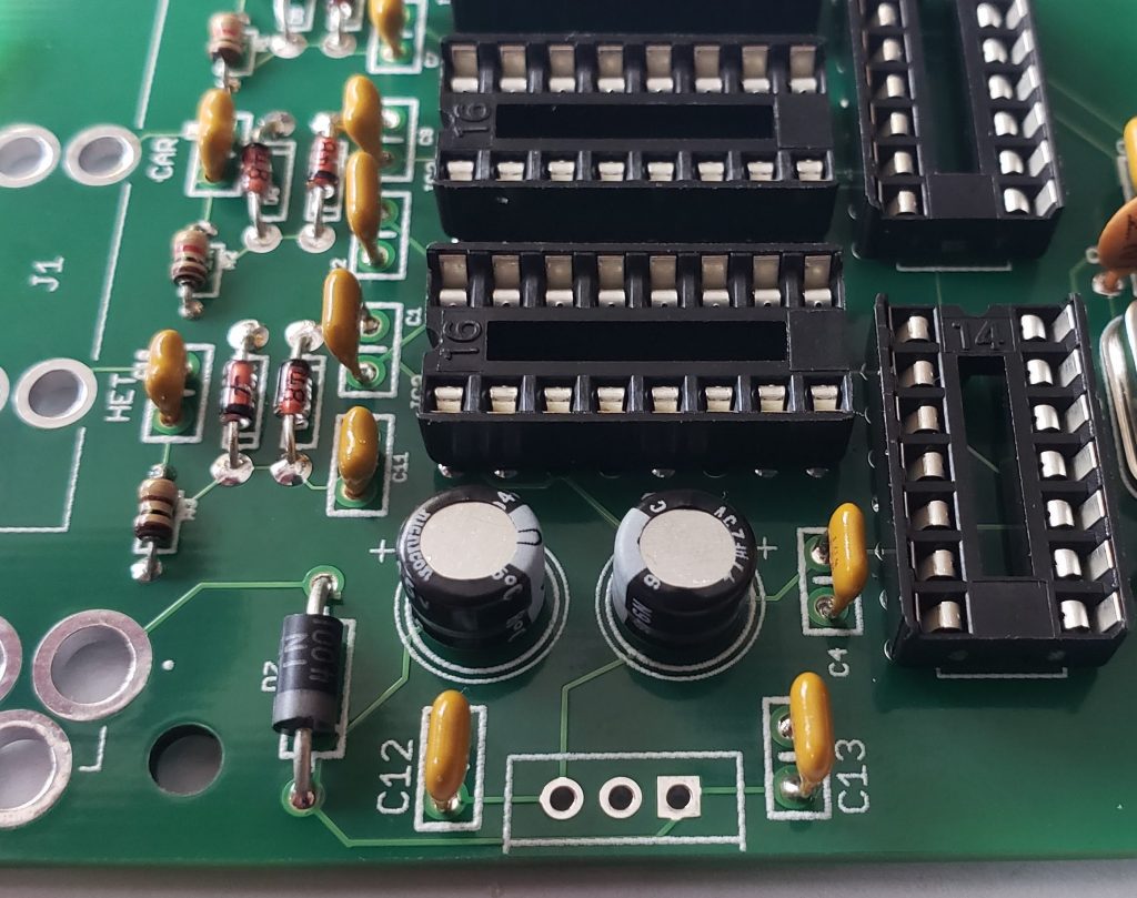
When both C18 and C19 are installed, the Negative sides should be facing each other as shown above.
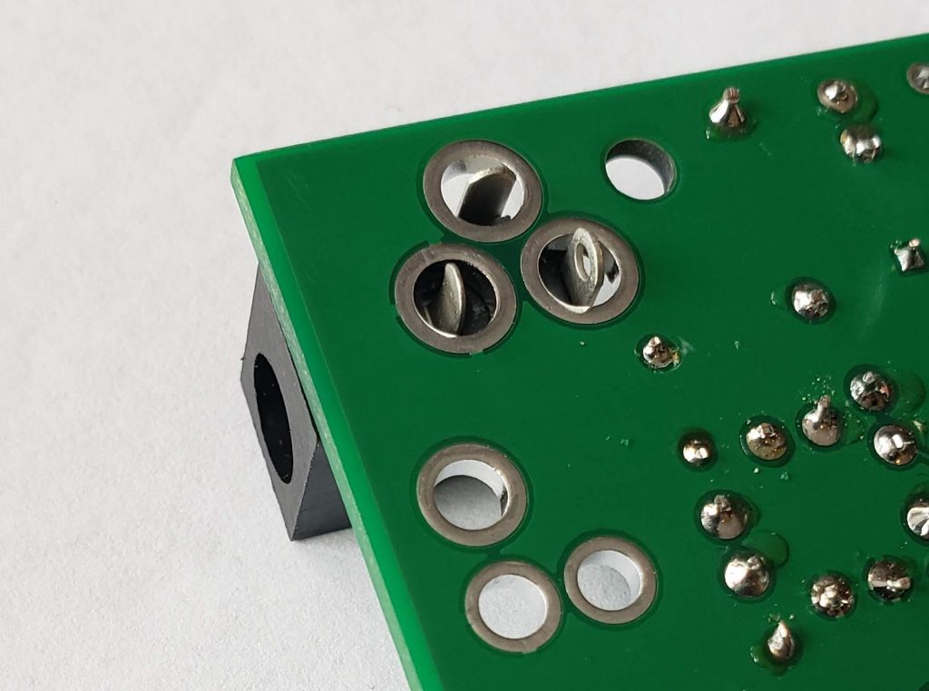
Fit the DC jack. It’s bit loose, I just solder it with plenty of solder, you could bend the tanks a little to hold better when soldering if you wish.
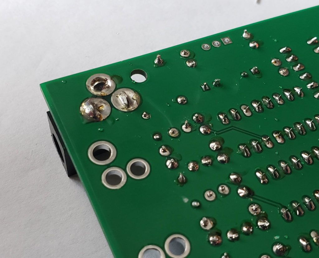
After soldering.
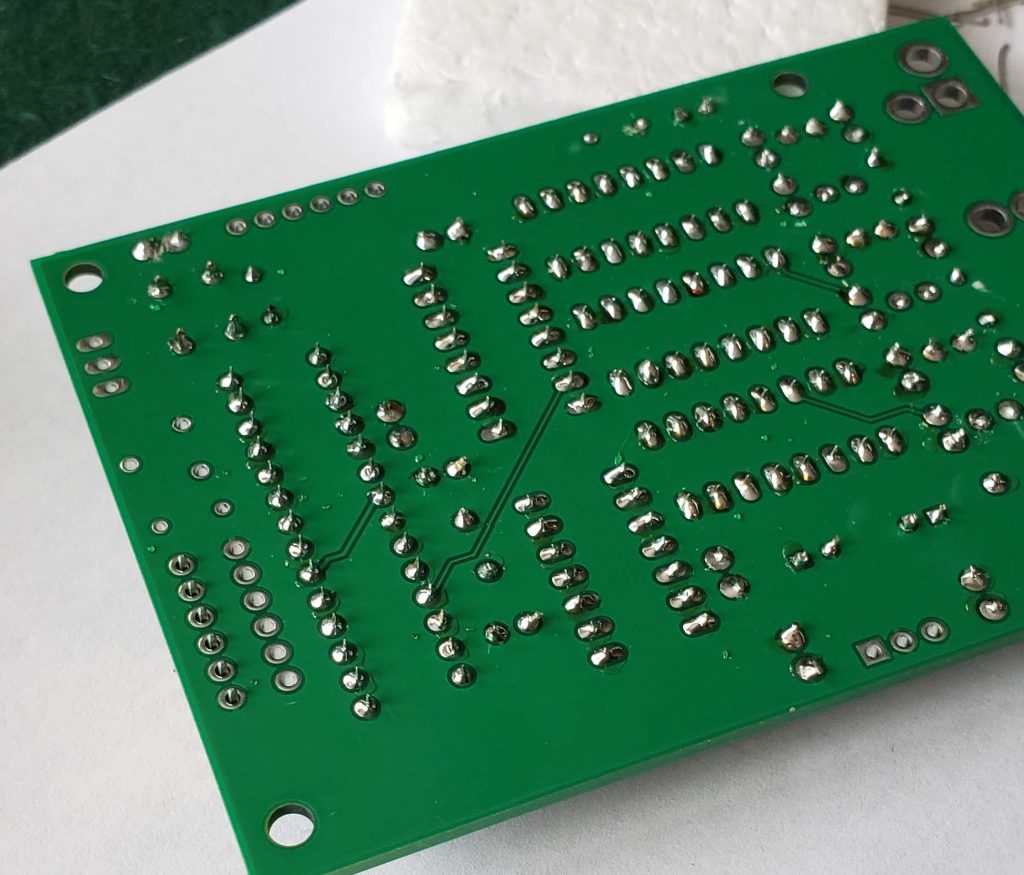
Pic above shows the display header LCD1 ready to be soldered. I solder one pin and check that it is perpendicular to the board before soldering the rest.
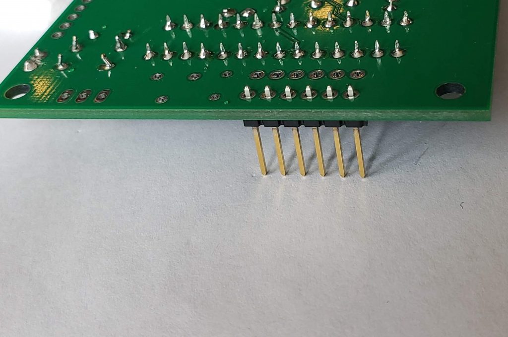
Another view
Solder all 3 6-pin headers in (LCD1, LCD2 and FTDI) and you board should look like the pic above
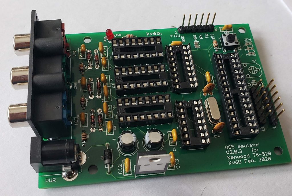
Add the triple RCA jacks and the 5V regulator (7805) and you should have a board looking like the pic above. Note, the flat back of the regulator faces out.
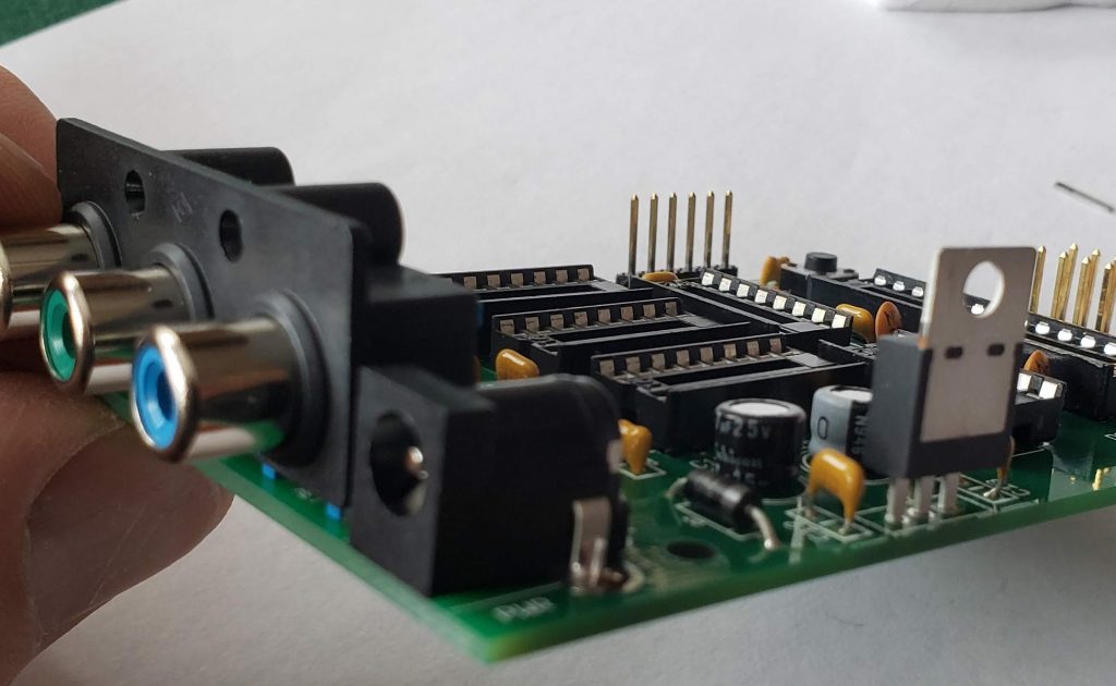
Another view
At this point, we’re ready to test the power supply of the board. We do this before we install the chips to keep from damaging them should we not have the proper 5V. Attach a DC supply to the DC input jack 8-15V is fine. The LED should light up. Next measure the 5V supply – there are multiple points you can do this at. I used LCD1, Pin 1 (GND) and LCD1, Pin 2 (+5V). I measured 5.0144V – good to proceed!
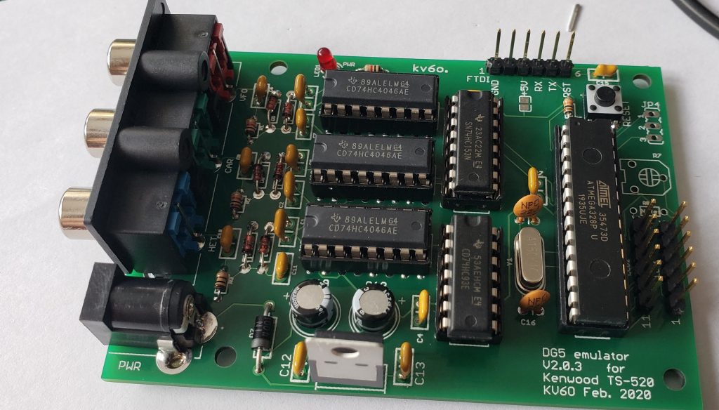
Install the chips. The 3 PLL’s (4046) are installed in positions IC1, IC2, and IC3, to the right of the RCA jacks and signal conditioning. IC4 is the 14 pin 74HC93 divide by 8 chip. IC5 is the 16 pin 74HC153 that selects the input to be measured. And lastly, U1 is the Atmel 328P. You will need to program this chip if you didn’t buy it from me! You can use a socket Arduino board and download the program using the Arduine IDE, then install the chip in the DG5 emulator if you wish.
We’re done with the build at this point, next step is to attached the appropriate display. For the LED display, we are going to use Pins 1 and 2 on the LCD1 row, and 11-13 on the LCD2 row.
- LCD1, Pin 1 – GND. Attach this to GND on the LED board
- LCD1, Pin 2 – +5V. Attach this to the VCC connection on the LED board
- LCD2, Pin 11 – Clock. Attach this to the CLK connection on the LED board
- LCD2, Pin 12 – Chip Select. Attach this to the CS connection on the LED board
- LED2, Pin 13 – Data In. Attach this to the DIN connection on the LED board
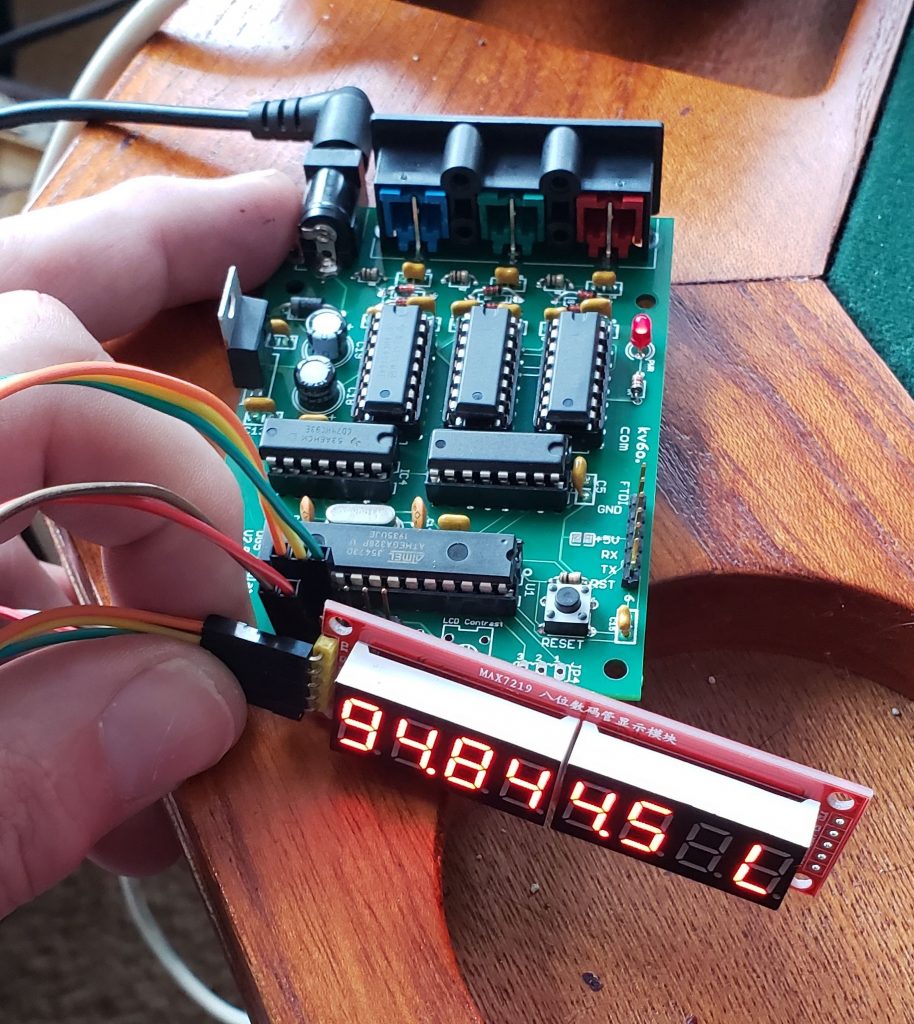
Once the connections are made, attach power and the LED should show “2.0.2” (or whatever version of code you’re using) for about a second, then display a nonsensical frequency (like the pic above) as there is nothing attached the the counter.
Install in a chassis, attach to your radio, and enjoy!
Steve/KV6O
UPDATE 5/10/2025 –
In addition to the instructions above, below is information on how to 3D print a front panel/bezel for a specific enclosure available on Amazon, and mounting instructions for this enclosure.
I have built several kits using the Eightwood Aluminum Electronic Project Box Enclosure Split Body Case DIY 4.72 x 3.82 x 1.57 inch (LxWxH). It looks like it’s been available for 10 years now (June 2015) so hopefully it will stick around.
I created a 3D printed front panel for this enclosure, you can find the STL file in the projects LED page on Github. There’s also two DXF files – “DG5-backplate.dxf” and “Chassis bottom 4 hole template.dxf”. These can be used to etch both nomenclature and cutouts for the back plate – I used my laser engraver to do this, then drilled and filed the openings. The “Chassis bottom 4 hole template.dxf” file can be used to cut out a cardstock template that will fit inside the enclosure and can be used to mark where to drill the 4 holes needed to mount the PCB. Use the actual PCB to verify that you have the correct side with the jacks flush against the rear of the enclosure. I used these M3x5mm+5mm standoffs to mount and position the PCB in the enclosure.
I’ll update this page with build pictures when I build another kit.