I have 3 kits put together like I sold in 2020, I’ll have 2 more avalable when I get more LED displays in a few days. For now, I’ll sell these for $60 plus shipping (probably about $5-$7 in the US). I can include the 3D printed front faceplate with a smoked acryllic insert for another $12 – I’ll include the 8 screws needed to mount the LED to the bezel/front panel and 4 to mount it to the enclosure. You can find the enclosure I used that this panel fits on Amazon here. I also have 2 fully built kits available at $135 each. For both the kit and built kit, you will need the cables to attach it to your radio – RCA patch cords (use video cables made for higher frequencies – not audio cables) and a power cable to supply 12V either from the TS-520S or an adapter.
I also have added 3 files to LED Github page. They are the 3D front plate should you want to print your own, and two dxf files that you can use with a laser engraver to position the PCB in the case, and to mark the cut outs for the back plate. Details at the bottom of the LED build page
SO, I am hoping to have 5 kits and 2 fully prebuilt “kits” ready to ship this week. Based on how these sell I’ll be able to order more parts for more shipments. Not sure if I’ll be able maintain the prices – we’ll see.
I am going to reach out to those who posted interest first via e-mail.
In From 2014 thru 2020, I sold the blank PCB for $8. In 2020, a kit including the LED display, PCB, and all the parts that were needed to be loaded on the PCB and a jumper to connect the two sold for $45. This included a preprogrammed (by me) ATmega328P and color printed instructions. Some of these were sold on eBay, for example, and there was 10% or so charges from them (don’t remember exactly) plus the PayPal fees, so I probably took in $38ish?
Today, just the parts I can get from Mouser – not including the LED display, jumper or PCB is almost $30 – $37.10 with shipping. Below is a sample of the price changes:
I’m not trying to make money with these kits, but I have to cover my costs, obviously. I am not ordering up one kit worth of parts at a time either, but now I am spending a couple of hundred dollars to make 8-10 kits. And I “make” them – count out the parts, load chips onto anti-static foam, load the parts in anti-static bags, program the microcontroller, etc.
I am probably looking at $60+ for a kit like the one I shipped in 2020 for $45. There’s an individual on eBay selling my design and building the same kit I described above (it’s open source after all) from the Netherlands for about $61 USD, about $75 shipped to the US. This is for a built PCB and display – not mounted in a case, but still – where does a $60 kit fit in here?
The extruded case from Amazon that I am using for my fully prebuilt kit is about $17, then I 3D print the front panel, cut out a piece of smoked acrylic to fit, hand tap and assemble the front panel. The back panel takes careful drilling with a small drill press, painting, engraving, filing – plus the time to build the PCB! Forgot drilling and mounting the PCB to the chassis with spacers, testing, etc. And the one I put up on eBay to “see what it’s worth” just sold for $102.51, shipping included. I can’t do that moving forward.
I am going to try selling a few kits like I did in 2020, with the option of the 3D printed front panel, and a few fully built kits as well…. we’ll see how this goes!
My last post here was in June 2020, almost 5 years ago now. What happened?
I shipped several hundred DG5 PCB’s and kits from 2014 thru probably 2021, when it really tapered off. And I got busy with, well, life and other stuff – so I just stopped working on this. I took my ham shack down a few years ago to accommodate some life changes, I have it partially up in a new location at the house, but that slowed down progress as well. New hobbies took over, and ham radio just hasn’t been what it was 10 years ago to me. My day job is running a 800MHz P25 system – so, in some ways I am “doing” radio for work – and that has slowed down the hobby for me. I still enjoy HF – just don’t get on as much anymore. I don’t have VHF/UHF in my cars anymore I first since becoming a ham over 20 years ago.
I do get requests here and there for a kit, and requests for a built unit. Previously, I sold the bare PCB, and a kit with all the components without a chassis. Some of the other hobbies that I have engaged in in the past 5 years have made it possible for me to offer a fully built unit – I think. I have been dabbling in 3D printing, and have also built a diode laser engraving table, and recently decided to see if I could make a built unit – and I have been working on that the past few weeks. I designed a front faceplate in Fusion 360 to accommodate the LED display, and using basic extruded aluminum chassis I think I have a unit I can reproduce in small numbers. My plan is to see if I can sell a few fully built units, then maybe have a full “kit” if there is a desire for one – PCB, components, and a chassis with front and rear faceplates. Selling a few fully built kits would allow me to purchase additional parts to make full kits – if there is a market for this – I dunno!
So… Step one will be to see if I can sell a pre-built “kit”. And that’s what it is – a DG5 kit that has been built and mounted in a aluminum chassis that has a 3D printed faceplate and a hand made backplate with the connectors. Not a commertial mass produced unit, and it shows. 🙂
Actually, I think the front, 3D printed plate looks pretty good – and that’s what you see when you’re using it anyway. The back plate with the holes drilled on my cheap drill press and filed by hand as needed – that’s still a work in progress. My laser works well at engraving the plate, but my metal fabrication skills are still lacking.
I tried an experiment back in March, and “kitted” up a few DG5 Emulators and put them on eBay. They sold, I bought more hardware to make more kits, they sold, and so on. So far, I have sold 25 kits, so I made a larger order today for the parts for another 20 rather than 5-10 at a time.
I have also almost exclusively sold them thru eBay, which has some pluses and minus. One big plus, is there is more exposure to folks looking for a DG5 there. International shipping appears to be easier and cheaper – I have sent kits internationally for $10 rather than the $17 or so it currently costs via USPS. They collect taxes for the State it ships to (not sure if this is a plus or a minus), and their order processing is as streamlined as it can get. Minus is the additional charges and fees they charge (on top of PayPal), which is why I have to charge more. Such is life I guess!
I was able to purchase a color printer, so now all the kits include 8 color pages of the build instructions. All in all, some life has been breathed into this project over the past 6-months. I’d like to come up with a case for the project, and do some more videos describing how it works – hopefully this summer!
Thanks for all the feedback, and I am currently out of stock as the last 2 sold today. It might take 2-3 weeks before I have the next 20 kits ready – the LED displays take the longest to source as they come from China.
The DG5 Project page has been updated with some new info, and new PayPal ordering buttons for both the old PCB (Version 1.5) and the new PCB (Version 2). There are also a very limited number of kits available, If the reception is good I’ll make up some more.
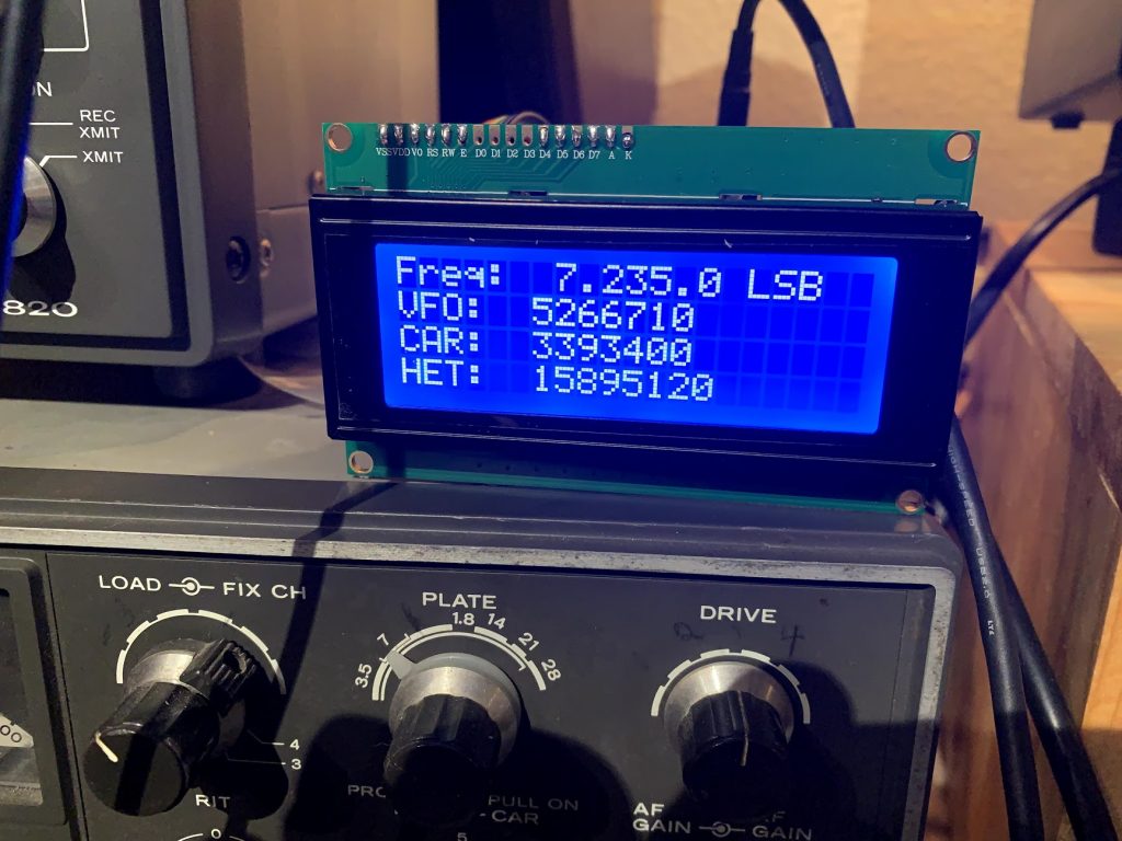
Lastly, a pic of a modified LCD version I loaded. I purchased a 4X20 LCD display for another project and decide to see about hooking it up to the DG5 and displaying more data:
The version 2.0.3 version of the PCB has arrived. I can ship the blank PCB and update the BOM so folks can order the parts, you’ll either need to have the capability of programming an Atmel 328P chip, or order up an Arduino UNO with one and pull the chip out of it after you download the program. I will work on putting together a few complete kits here as well as I have the parts – this would include a pre-programmed 328P. I might sell the PCB with the pre-programmed 328P as well – I guess I need to see what people want! Comments welcome!
Since I don’t have the BOM updated yet, and I don’t have a way to order, please either leave a comment or send me an e-mail (mycall@mycall.com) and we can figure it out.
UPDATE 3/8/20 – I have updated the Bill of Materials (BOM), schematic, and Eagle files on DG5 GitHub Project Page Click on the PCB link to see the files.
I have ordered up parts for 10 kits, and will hopefully be able to sell them soon. If you are looking to order a new board, please e-mail me (mycall@mycall.com) as you might want to also purchase a pre-programmed Atmel 328P, a 10ppm crystal (currently back-ordered on Mouser), etc. I’ll hopefully get a better Paypal ordering system going here soon.
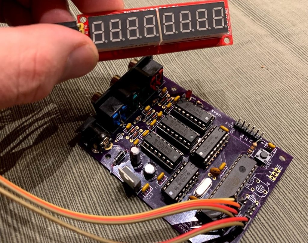
The new DG5 emulator board (with Atmel 328p on board) arrived Saturday, and I put one together today. It looks good, the only issues were 2 caps were not labeled (silk-screened) on the board. Worked the first time.
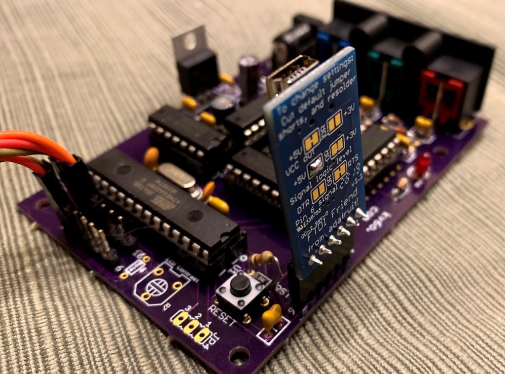
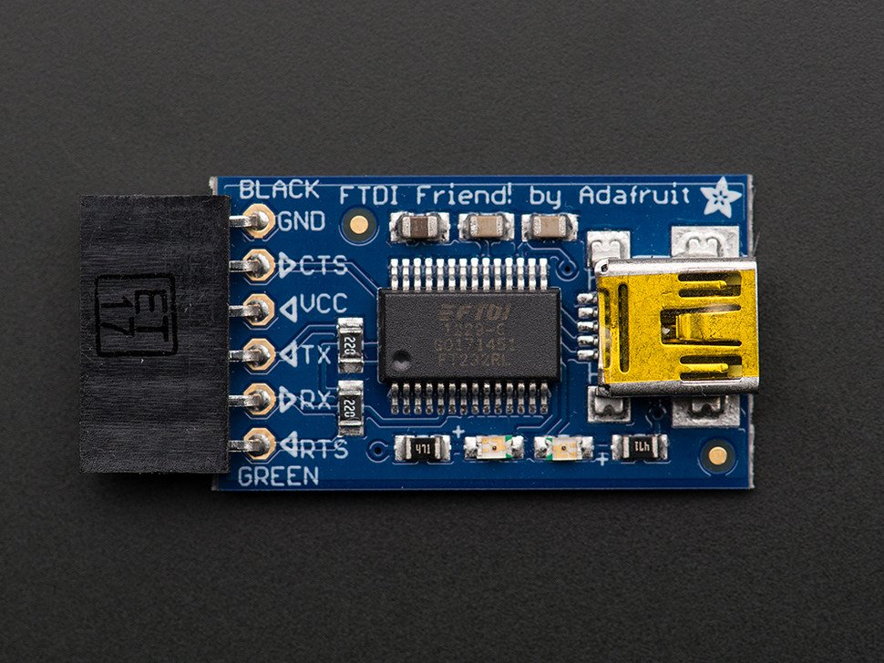
Since there isn’t an Arduino board involved, there us no USB port to program the micro-controller. Instead, there is a FTDI header that allows you to plug in a USB to TTL converter – I am using one from Adafruit called the FTDI Friend. It includes a reset line wired to RTS, which allows the Arduino IDE to be able to program it. The board is wired to allow this to plug directly in for programming, other FTDI boards should work but might need a cross connecting wire to get the signals (TX/RX/GND/RESET) going to the right places. And the Atmel processor will need an Arduino bootloader for this to work anyway. There are a couple of ways to handle this.
Buy (or use existing) Arduino with a socketed, 28pin Atmel 328p like the UNO to program the chip.
Buy a pre-programmed 328p chip from me with either the LED, LCD, or NIXIE code pre-loaded.
If you already have an Arduino UNO or similar, you can program the chip, remove it and install it in this board. If you buy the chip from me, you don’t need an Arduino. You don’t need the FTDI board either, but you won’t be able to connect to it to enable debugging if necessary, or be able to update the code in the future.
Some pics:
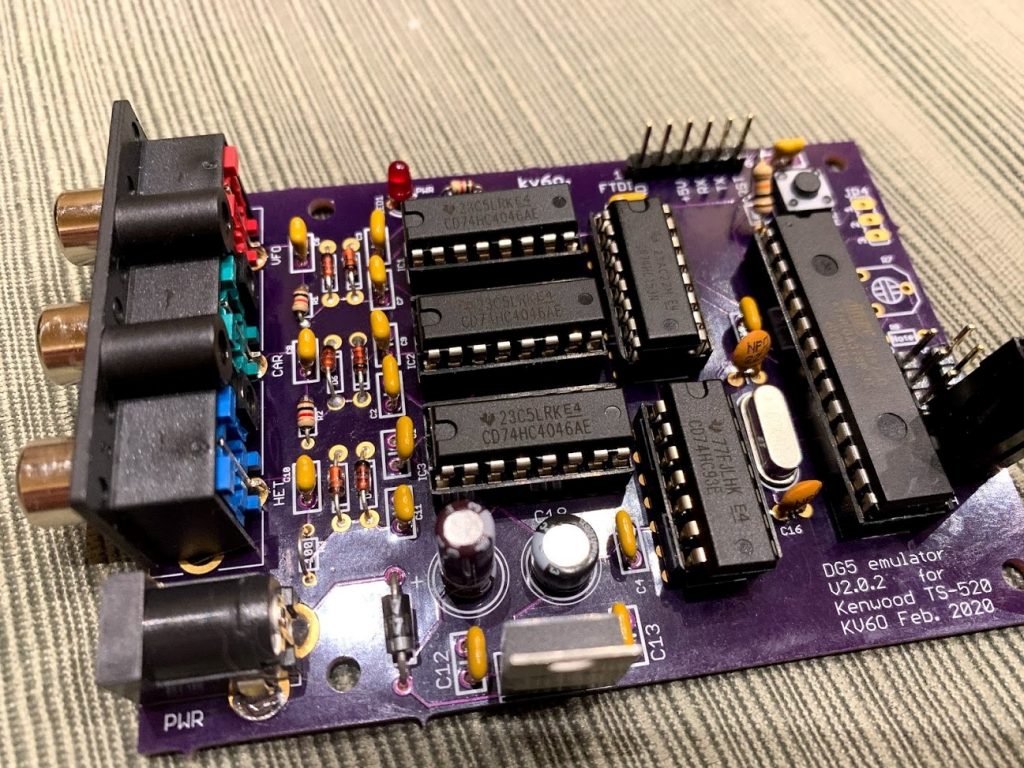
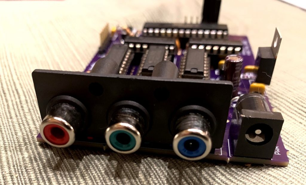
The populated board, version 2.0.2The new RCA triple ganged jackWith the FTDI adapter plugged inBoard attached to LED module
I corrected the missing silkscreen labels, and added a solderable pad to the 5V line on the FTDI header. You don’t want the 5V from the FTDI board mixing with the 5V on the board – the linear regulator provides nice, clean power, and when the 5V from the FTDI board was connected, the displayed frequency jumped around. As soon as I disconnected the 5V from the FTDI board, it wen’t back to smooth operation. The solderable pad will allow you to bring 5V to this pin – I will be trying a FTDI/Bluetooth board that will need power in the future.
I am thinking about kitting (include all parts except case/chassis) up a couple of these boards with the parts I have on hand, I’ll have to add up the costs and come up with a price. If there is a lot of interest in having it kitted, I’ll see what I can do. I am not trying to run a business here, and I don’t want to get sucked into a huge time waster, but this is a fun project and I am willing to make it a little easier to get off the ground. Let me know your thoughts in the comments!
Lastly, I have the one built prototype board, and have 2 more PCBs. I might build them, and put them on eBay to see what happens, no chassis, just the populated and working board as seen above. I’ll make a post here if I do!
Dave Johnson, WB4JTT has written up a document on how to use the DG5 emulator as a Heathkit SB-650 emulator! The Heathkit SB-650 is an external Nixie tube display, much like the Kenwood DG5. In fact, it uses the same 3 frequency scheme as the DG5.
The prototypes I received had a few issues – I neglected to add filtering caps for the supply as the original design didn’t need it – the Arduino host board had them. I also had a couple of wiring errors. The bigger issue was the lack of availability of another part – the three RCA connectors. It turns out that SparkFun no longer has these parts, and when I checked with their supplier (4UCON) the minimum order was 3000 pieces. Not happening.
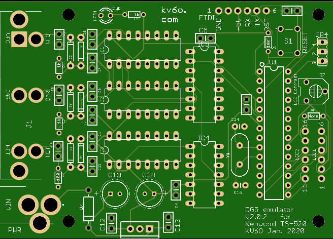
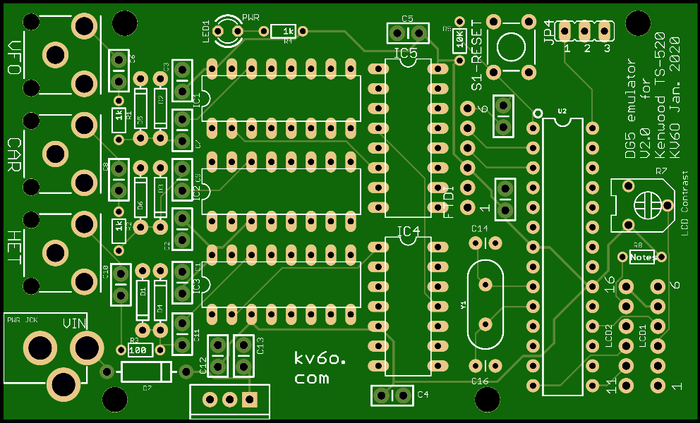
Version 2.0.2 has some corrections, and incorporates a triple RCA connector that is available from Mouser. The jacks are spread out a little further as well, which is probably a good thing as the original was pretty tight due to the limitations of the Arduino Shield size. The 2.0.2 version is a little wider as well as longer.
The board is now 3.5″ X 2.5″.
I’ll order another set of prototypes to test, and hopefully be able to make a larger order to make available. The existing shield based version still works just fine, you just need to source a Arduino Duemilanove (or equivalent), and solder coax jumpers to panel mount RCA’s as the PCB mount RCA’s the board is designed for are unavailable.
I am working on an updated design to the DG5. Rather than being a shield for an Arduino, this PCB has the Atmel 328P chip on the board, along with room for a proper crystal, reset switch, and FTDI programming header. The main reason for doing this is the preferred Arduino to use – the Duemilanove – is getting pretty hard to find as this was a 2009 model. The later boards all use a ceramic resonator as the clock for the chip – which isn’t nearly accurate or stable enough in the role of a frequency counter.
The input side of the board is unchanged, the Arduino Shield headers have been removed and some rearranging of IC4 & IC5 to better allow the addition of the Atmel 328P (what is used on the Arduino’s) and the supporting hardware.
There is no USB port on this board. It would best to still have an Arduino to be able to load the software, as the bootloader comes on the chip when you buy an Arduino. If you have a chip programmer, you can do this without an Arduino. Once the chip has an Arduino bootloader, you can program via the FTDI header – a TTL interface that works with something like this from Adafruit:
More to come, I just sent off for a set of prototype boards. There is no advantage upgrade if you already have the shield working – this is to address the lack of crystal controlled Arduinos moving forward if all goes well. This also means you’ll need to have a programmer or arduino anyway – and need one of these FTDI boards (above) that cost as much as an Arduino anyway.