
The DG5 version 2 addresses a couple of supply issues the Arduino shield version has. Neither make version 2 any better than the existing version 1.5. They both work the same way and run the same code. The main reason for doing this is the preferred Arduino to use – the Duemilanove – is getting pretty hard to find as this was a 2009 model. The later boards all use a ceramic resonator as the clock for the chip – which isn’t nearly accurate or stable enough in the role of a frequency counter.
The second reason is the RCA jacks used with version 1.5 are no longer available. The first prototype (V2.0) used the old style RCA jacks, and was missing some properly sized electrolytic caps at the regulator. The shield attached to an Arduino, which provided this.
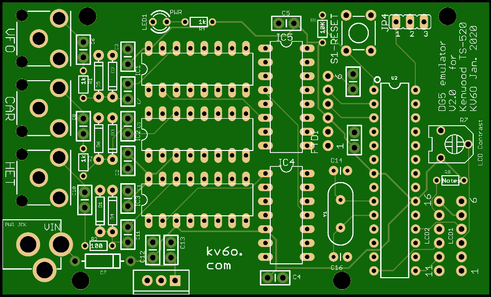
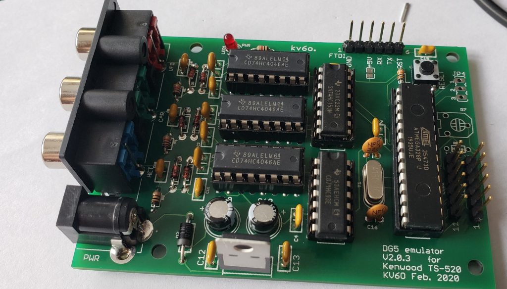
The next prototype was a little bit wider to incorporate the new, triple ganged RCA jack, and added in the 47uF caps. The shield version’s RCA jack spacing was a bit tight – some cables could be problematic getting on and off. After a few minor corrections, the “production” run is version 2.0.3
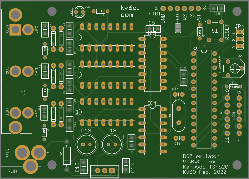
The input side of the board is unchanged.
There is no USB port on this board. It would best to still have an Arduino to be able to load the software, as the bootloader comes on the chip when you buy an Arduino. If you have a chip programmer, you can do this without an Arduino. Once the chip has an Arduino bootloader, you can program via the FTDI header – a TTL interface that works with something like this from Adafruit:
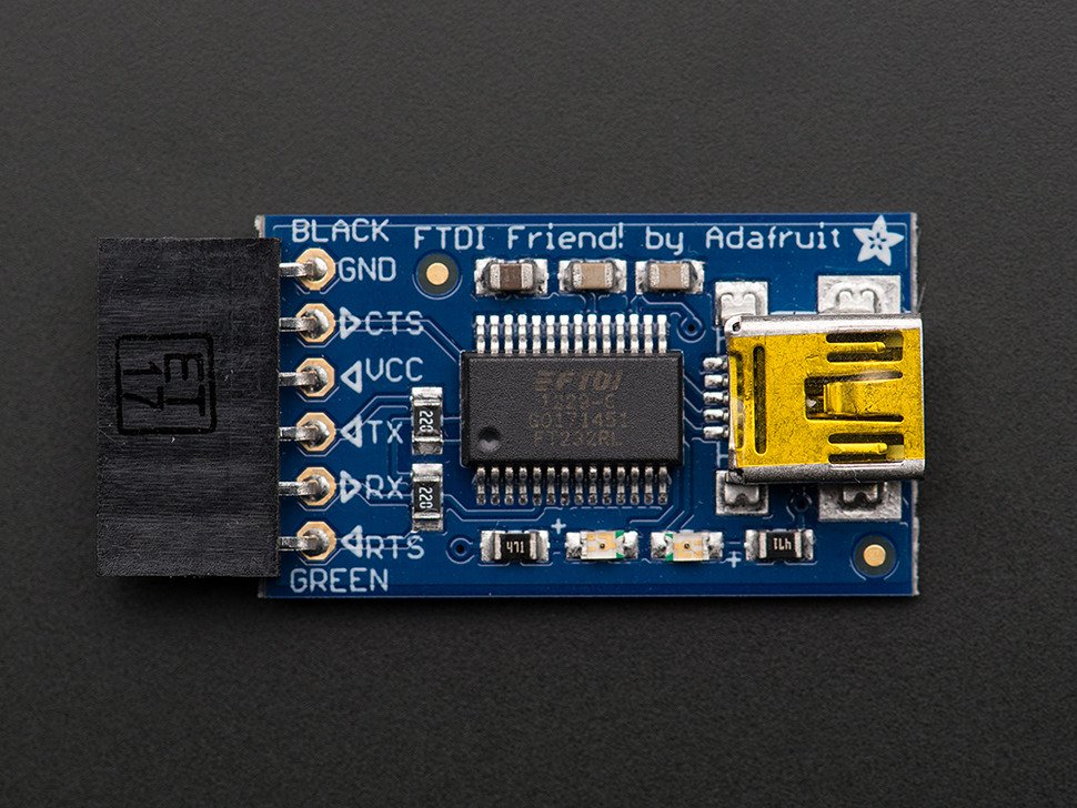
Once you have a bootloader installed on the 328P, you can upload code using this board plugged into the FTDI port.
You can order this PCB and maybe the kit (if I have any) on the main project page.
The schematic and Eagle files can be found on GitHub