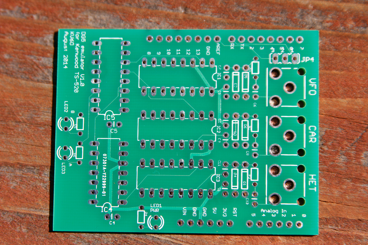
Yippie! The boards arrived last week and it was a few day’s before I could get to them. They sure looked nice!
I was working on version 1.1 of the layout before these boards even arrived as I realized that the inputs for the VFO/CAR/HET were on the opposite side of the board from the USB connector – not convenient if you want to mount the assembly in a chassis. But I was anxious to get this first version up and running to see if I got the schematic correct in Eagle. And as is usual, I found a couple of minor problems.
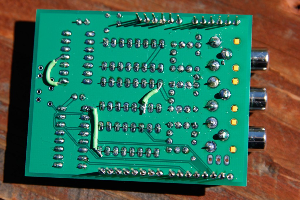
Here’s a view of the bottom of the populated board – note the 3 jumpers. Turns out I made a few mistakes – one was bringing a NET on the Eagle schematic over the pin and near the chip – missing the intended connection to the pin. Another one was missing an air wire – a ground “island” was created without a connection to ground. And lastly, I wired to the wrong output pin on the 74LS93 counter, winding up dividing by 4 rather than 8. All three errors were corrected with jumpers.
There is also some silkscreen mistakes, I somehow incorrectly labeled the Arduino shield pins in two areas – not critical.

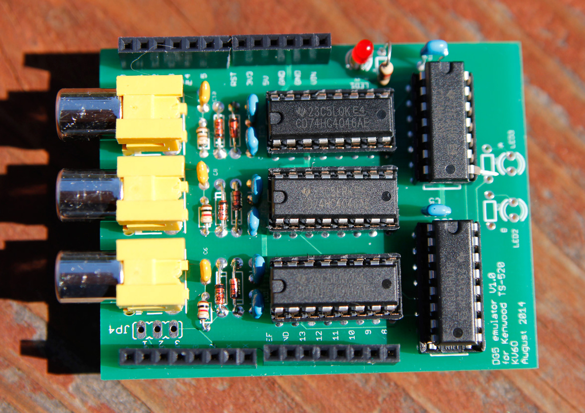
Here’s the board fully populated from the top.
Few other issues with this version that I have corrected with version 1.1:
- Some of the Eagle parts used solder pads that are pretty small, making soldering a little more difficult.
- I had 2 LED’s for showing which input was selected on the LS74153, which I have removed in version 1.1 to save board space, they weren’t really necessary.
As I work on the new version in Eagle, I am trying to keep in mind a few other things now that I have an actual, working shield.
- Arduino to shield clearance – putting the RCA connectors on the same side as the USB connector makes it easy to short things out. A little bit of electrical tape on top of the USB connector should prevent this.
- Need to keep the PLL output signals as short as possible as they are 5V TTL level representations of the original, low level signals – a potential RFI issue. Using the shield design this isn’t really possible as the signal exits the shield to the main Arduino board on Pin 5. A better design would put everything on one PCB, keeping HF signals nets as short as possible. Another way of reducing this issue as a good, shielded enclosure.
- Might need to add an LM7805 so it can run without being connected to the computer via USB. I added one to my original prototype since it has an LCD display and isn’t dependent on a computer. The LCD’s backlight and the Arduino draw enough current that a good heat sink is required to drop the 13.8VDC (provided at the back of the TS-520 for the DG5) to 5VDC.
Arduino’s with shields don’t lend themselves well to enclosures, so one possibility might be to make a larger shield that an Arduino plugs into that can slide into an extruded aluminum enclosure. The Arduino would be a “daughter card” in this scenario, plugged in up side down on the main board.
My TS-520 still uses the prototype shown below since it’s already mounted in an enclosure and has the LCD display added, which was something I added after I sent in the version 1.0 PCB design.
[gview file=”https://www.kv6o.com/wordpress/wp-content/uploads/2014/09/DG5-shield_v1_2_schematic.pdf” save=”1″]
My current schematic, with 2, 6-pin jumpers to go to a 16-pin LCD display (only the first 6, and last 6 pins are used on the display).
Latest Arduino code with LCD support (note the pins used for the LCD):
[wpdm_file id=3]
Note – I have only tested this with the Arduino UNO and Duemilanove boards. There are probably issues with other Arduino boards, such as the Leonardo, as they use the internal TIMERs for USB emulation.
If you’re interested in the eagle files, drop me a line.