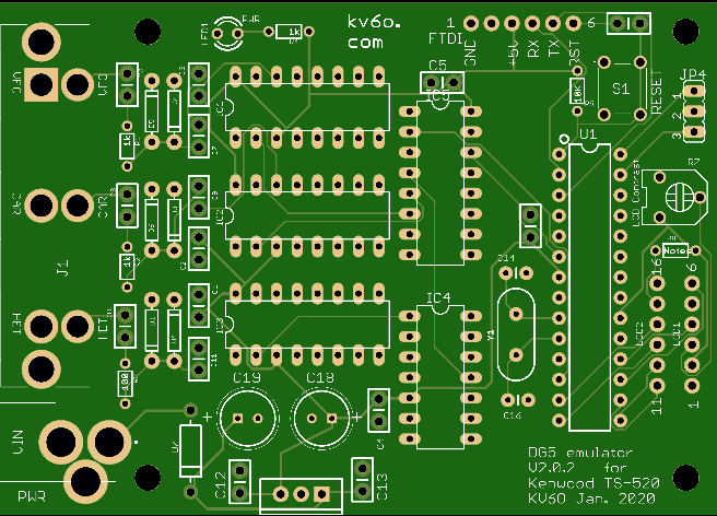
The new DG5 emulator board (with Atmel 328p on board) arrived Saturday, and I put one together today. It looks good, the only issues were 2 caps were not labeled (silk-screened) on the board. Worked the first time.
Since there isn’t an Arduino board involved, there us no USB port to program the micro-controller. Instead, there is a FTDI header that allows you to plug in a USB to TTL converter – I am using one from Adafruit called the FTDI Friend. It includes a reset line wired to RTS, which allows the Arduino IDE to be able to program it. The board is wired to allow this to plug directly in for programming, other FTDI boards should work but might need a cross connecting wire to get the signals (TX/RX/GND/RESET) going to the right places. And the Atmel processor will need an Arduino bootloader for this to work anyway. There are a couple of ways to handle this.
- Buy (or use existing) Arduino with a socketed, 28pin Atmel 328p like the UNO to program the chip.
- Buy a pre-programmed 328p chip from me with either the LED, LCD, or NIXIE code pre-loaded.
If you already have an Arduino UNO or similar, you can program the chip, remove it and install it in this board. If you buy the chip from me, you don’t need an Arduino. You don’t need the FTDI board either, but you won’t be able to connect to it to enable debugging if necessary, or be able to update the code in the future.
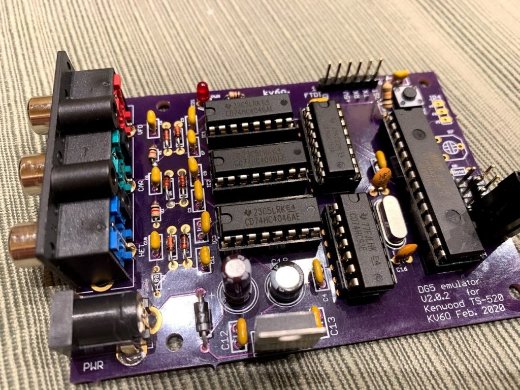
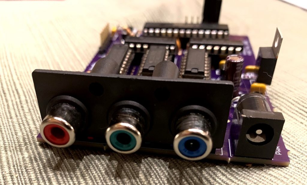
Some pics:
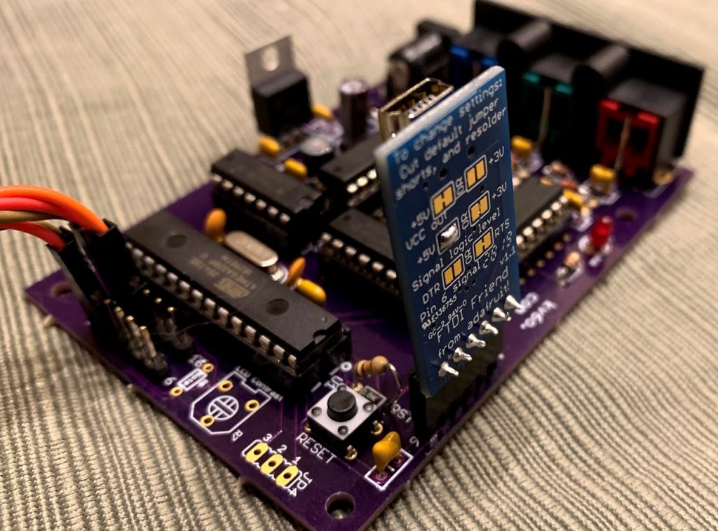
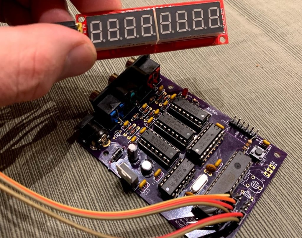
I corrected the missing silkscreen labels, and added a solderable pad to the 5V line on the FTDI header. You don’t want the 5V from the FTDI board mixing with the 5V on the board – the linear regulator provides nice, clean power, and when the 5V from the FTDI board was connected, the displayed frequency jumped around. As soon as I disconnected the 5V from the FTDI board, it wen’t back to smooth operation. The solderable pad will allow you to bring 5V to this pin – I will be trying a FTDI/Bluetooth board that will need power in the future.
I am thinking about kitting (include all parts except case/chassis) up a couple of these boards with the parts I have on hand, I’ll have to add up the costs and come up with a price. If there is a lot of interest in having it kitted, I’ll see what I can do. I am not trying to run a business here, and I don’t want to get sucked into a huge time waster, but this is a fun project and I am willing to make it a little easier to get off the ground. Let me know your thoughts in the comments!
Lastly, I have the one built prototype board, and have 2 more PCBs. I might build them, and put them on eBay to see what happens, no chassis, just the populated and working board as seen above. I’ll make a post here if I do!