
Yippie! The boards arrived last week and it was a few day’s before I could get to them. They sure looked nice!
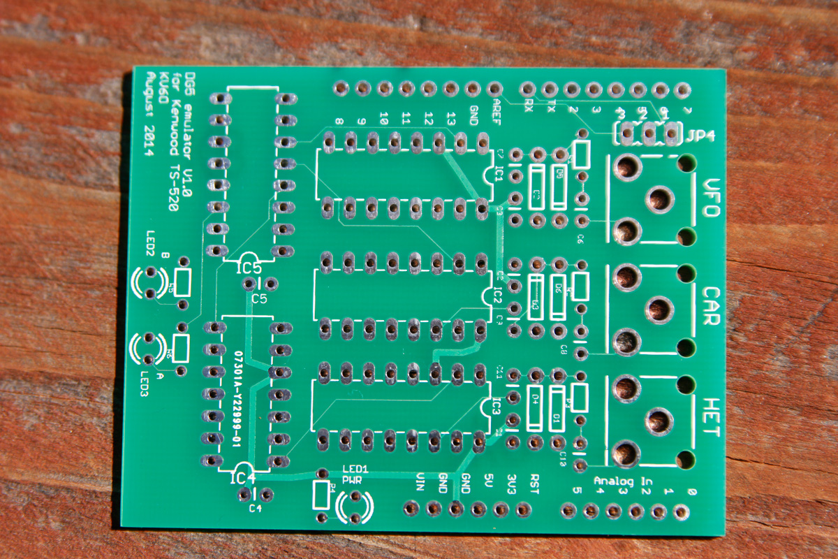
I was working on version 1.1 of the layout before these boards even arrived as I realized that the inputs for the VFO/CAR/HET were on the opposite side of the board from the USB connector – not convenient if you want to mount the assembly in a chassis. But I was anxious to get this first version up and running to see if I got the schematic correct in Eagle. And as is usual, I found a couple of minor problems.
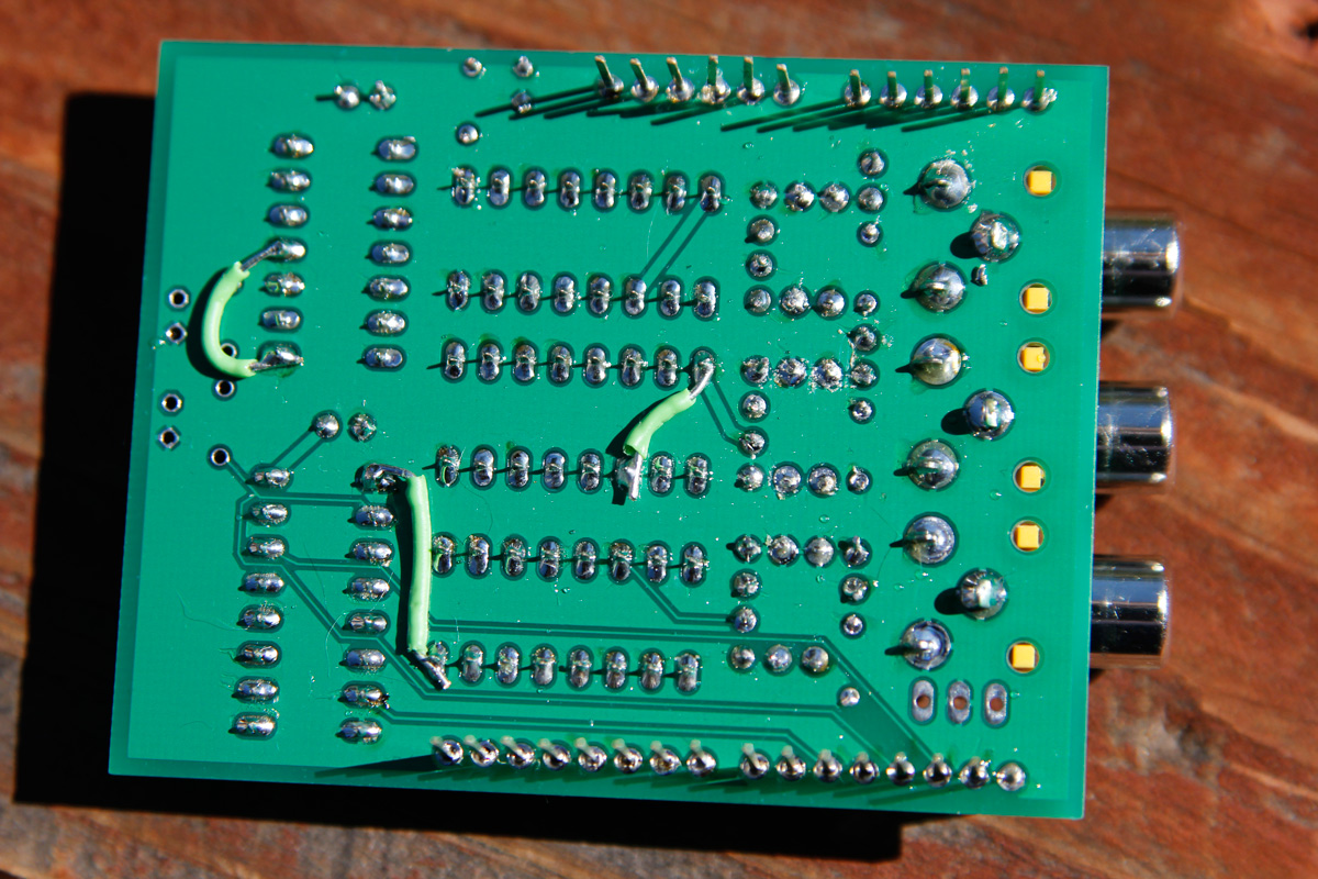
Here’s a view of the bottom of the populated board – note the 3 jumpers. Turns out I made a few mistakes – one was bringing a NET on the Eagle schematic over the pin and near the chip – missing the intended connection to the pin. Another one was missing an air wire – a ground “island” was created without a connection to ground. And lastly, I wired to the wrong output pin on the 74LS93 counter, winding up dividing by 4 rather than 8. All three errors were corrected with jumpers.
There is also some silkscreen mistakes, I somehow incorrectly labeled the Arduino shield pins in two areas – not critical.
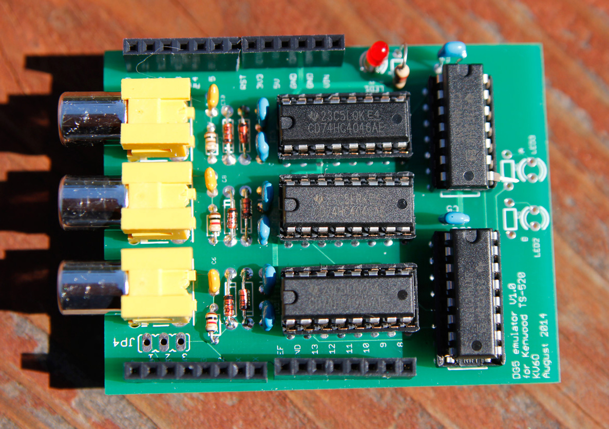
Here’s the board fully populated from the top.
Few other issues with this version that I have corrected with version 1.1:
- Some of the Eagle parts used solder pads that are pretty small, making soldering a little more difficult.
- I had 2 LED’s for showing which input was selected on the LS74153, which I have removed in version 1.1 to save board space, they weren’t really necessary.
As I work on the new version in Eagle, I am trying to keep in mind a few other things now that I have an actual, working shield.
- Arduino to shield clearance – putting the RCA connectors on the same side as the USB connector makes it easy to short things out. A little bit of electrical tape on top of the USB connector should prevent this.
- Need to keep the PLL output signals as short as possible as they are 5V TTL level representations of the original, low level signals – a potential RFI issue. Using the shield design this isn’t really possible as the signal exits the shield to the main Arduino board on Pin 5. A better design would put everything on one PCB, keeping HF signals nets as short as possible. Another way of reducing this issue as a good, shielded enclosure.
- Might need to add an LM7805 so it can run without being connected to the computer via USB. I added one to my original prototype since it has an LCD display and isn’t dependent on a computer. The LCD’s backlight and the Arduino draw enough current that a good heat sink is required to drop the 13.8VDC (provided at the back of the TS-520 for the DG5) to 5VDC.
Arduino’s with shields don’t lend themselves well to enclosures, so one possibility might be to make a larger shield that an Arduino plugs into that can slide into an extruded aluminum enclosure. The Arduino would be a “daughter card” in this scenario, plugged in up side down on the main board.
My TS-520 still uses the prototype shown below since it’s already mounted in an enclosure and has the LCD display added, which was something I added after I sent in the version 1.0 PCB design.
[gview file=”https://www.kv6o.com/wordpress/wp-content/uploads/2014/09/DG5-shield_v1_2_schematic.pdf” save=”1″]
My current schematic, with 2, 6-pin jumpers to go to a 16-pin LCD display (only the first 6, and last 6 pins are used on the display).
Latest Arduino code with LCD support (note the pins used for the LCD):
[wpdm_file id=3]
Note – I have only tested this with the Arduino UNO and Duemilanove boards. There are probably issues with other Arduino boards, such as the Leonardo, as they use the internal TIMERs for USB emulation.
If you’re interested in the eagle files, drop me a line.
Would be very interested in the Eagle files. If I understand correctly, the schematic is 100%, just layout etc that was tweaked for V1.1/V1.2?
Nathan KK4REY
Give me a few days, I am still tweaking the design and hopefully will have it nailed down soon and will send off for PCB’s. I can share the V1 design with known errors and no LCD support on the board, but your probably better off with the next version which will have all the connectors on one side, LCD connectors, and errors fixed, with no new ones (hopefully).
Steve
KV6O
Interesting approach.
I have designed a replacement board for the DG5 main board. It uses a PIC for the conversion math and display and some external counters. The external counters allow a fast update time (as fast or faster than the original DG5). I struggled with multiplexing the inputs and getting an acceptable update time.
It drives the original 7 segment LED displays. Another version works with an LCD.
The counters are cheap and I have designed a pc board. Health issues have prevented me from pursuing the project lately. I will be purchasing some test boards in the next month. The intention was to make it so that the old main board would be removed and this board inserted into the DG5 case. Prototypes work great. I have hand built a couple dozen for friends.
Nice work
Tim
KD8CN
Wow – that sounds pretty cool! What external counter ship did you use? I looked around and I couldn’t find anything that seemed appropriate, I did see some folks implementing ring counters in CPLD SMD devices, that could have off loaded the counting work. The 328p chip uses 2 timers for the counting, and can’t respond to interrupts during a count (or use the timers, obviously), so I am limited in what else the chip can do. Offloading the counting might allow the 328p to handle other things, like maybe running a AD9850 DDS chip for an external VFO!
Steve
KV6O
Hey, just re-found your page here. I have boards and packages I am selling. The PIC version of the TS-520 DG5 (I call it my CN-5) is selling well. I have a frequency display for the FT-101 Yaseu rigs. I also have a DDS VFO that works with Johnson transmitters, also as a remote for Kenwood TS-520s and TS-820, and Heath. It also can be used as crystal synthe sizer. Its based on an Arduino NAno. The arduinos are not good as frequency displays, but work well as synthesizers.
I have also developed software to use the DDS as a Master Oscillator for Hammarlund, Hallicrafters, Collins etc receivers. MAkes the receives work like a solid state digital rig.
I now have boards and kits for all of these.
73
KD8CN
Wow – very nice! Do you have a link for your website? I played around with some code for a DDS based VFO and had it working, but never finished it.
Wow! And I was just considering putting a digital VFO display on my ts-520s. I’m looking forward to your future posts. Keep up the good work and I hope you feel better soon.
I’m not sure what the eagle? 73’s,
Pedro
WA4KEO
Pedro – I am not sure what you’re asking – Eagle was used to design the PCB, is that what you’re asking?
Steve
KV6O
Yes. Sounds like CAD for pcb design. Just never heard before. 73’s, Pedro
Good answer; sounds like some form of CAD.
Question: Is the program for the DG5 emulator available on disk?
73’s,
Pedro
WA4KEO
Code is on Github – https://github.com/sleander1/DG5