
UPDATE 3/15/2020: I have moved the old DG5 emulator page to this page, called “DG5 Shield V1.5” for the Arduino shield version of the project. There is a stand alone version (2.0.3) that doesn’t use an Arduino, and has some new parts that are currently available.
UPDATE 4/8/17 – I have split this project into 3 pages each one dedicated to the 3 display variations, the LCD version, the LED version, and the NIXIE version. The LCD project page doesn’t contain too much as most of it is below – it’s the original version I built. The LED version came next because the original DG5 had LED’s, and it looks a little more period correct, and the Nixie version because Nixies are waaay cool and really look the part!
Original post: 10/17/2014:
A few months ago I bought a Kenwood TS-520S, and was just having a blast making contacts with it. The one thing I really missed from my more modern rigs was the computer interface. My logging software would read the frequency and mode from my other rigs which made logging easy, and relatively error free. I noticed that as I used the TS-520S I would often forget to record the frequency (or record it wrong) as I had to manually enter this info in. Not a big deal, but I guess I am lazy and spoiled, so I thought I’d look to see if I could emulate a DG5 with the Arduino platform and add a computer interface.
The Kenwood DG5 Emulator described here is an Arduino based “digital dial” display for the Kenwood TS-520S and possibly the TS-820 – I don’t have one to test with. The Kenwood DG5 was an accessory sold by Kenwood that added a digital LED display to the TS-520S. Every once and a while these are available for sale on places like eBay, but they often sell for more than I paid for the radio. Plus, they have a history of issues, and they don’t interface to a computer.
While poking around on the web for a solution, I found a series of posts Todd Harrison had done over at ToddFun.com – definitely check it out if you’ve read this far. He had figured out how to build a DG5 emulator using 3 PLL chips to buffer and condition the 3 signals the TS-520 outputs to the DG5. I built one up and wrote some code, and presto – I had a TS-520S with a USB port! I had a PCB made, improved the code, fixed errors that came up, and another PCB made and here we are.
It’s built as a “shield” for the Arduino Duemilanove, an ATmega328 based board. It will not work with the newer, Leonardo based Arduino as it uses a different chip (ATmegaXU4) which is not compatible. While the UNO should work as it’s based on the same chip (but has a few extra pins and features) I have not tested with the UNO. 11/4/14 – Note that the UNO uses a ceramic resonator for it’s clock oscillator – fine if you want to blink some LED’s, but not suitable for a frequency counter where accuracy and stability are very important. I recommend a Arduino Duemilanove (which uses a crystal oscillator) – they can still be purchased at Amazon for around $20, or around $10 on eBay from China.
Here are the posts of the projects progress:
A Kenwood DG-5 emulated on Arduino
DG5 Update – now with LCD display!
Arduino based Kenwood DG5 emulator for my TS-520S
DG5 emulator Version 1 PCB’s have arrived
DG5 emulator version 1.4 ready to go!
DG5 Emulator Version 1.5 PCB’s have arrived!
I also have a post about a DDS VFO that I have been working on, at some point I think I’ll be able to integrate the two with one Arduino (I have rough code running), but for now I am focusing on the DG5 project.
I have decided to make the entire thing open source as I have benefited greatly from others who have done the same. Additionally, as folks build and use this shield there will be improvements made by the users – this is just a starting point. I do have PCB’s available for purchase, if you’re interested, see below near the end – there is a Buy Now button to order a PCB.
Now on to the good stuff…
[gview file=”https://www.kv6o.com/wordpress/wp-content/uploads/2014/10/DG5-shield_v1_5.pdf” save=”1″]
This is version 1.5 of the schematic. You can download it separately here, or download it as part of the project file, including the Eagle files and Arduino code at the bottom of the page.
As for parts, I used what I had, and ordered up some from Mouser and SparkFun. SparkFun supplied some of the Eagle footprints for parts like the RCA connectors – it’s only fair to buy them from them!
Here are the parts needed to complete the project (besides the PCB, and Arduino, a soldering iron, solder, a TS-520S, etc.) Adjust as needed – your parts bin might have much of this stuff:
http://www.mouser.com/ProjectManager/ProjectDetail.aspx?AccessID=03394fdd5d – Mouser parts, includes most of the components. http://sfe.io/w97558 – SparkFun parts, includes RCA jacks, LCD display, 4″ jumpers for the display, etc.The LCD is the most expensive part in the build (besides an Arduino), if you have one already the parts are about $20. Less if you have a well stocked parts bin. Arduino’s can be had for less than $10 on eBay, and the LCD display (a 16×2, HD44780 based display – very common) can be had for a few bucks if you look around and can wait on shipping.
Build instructions:
The next time I build one I’ll better document the build instructions, but it’s pretty straight forward.
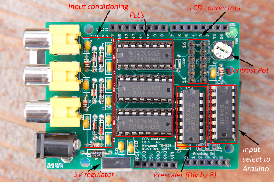
Looking down on the top of the board, first solder in the capacitors, resistors, and diodes – the smallest components. The diodes (4148’s) in the input conditioning section are there for protection of the PLL’s from high input voltages, and go in “back to back” – look at the silkscreen for the correct orientation. There are 3 resistors in the input conditioning section on the left, 2, 1k ohm resistors (R1 and R2) and 1, 100 ohm (R3).
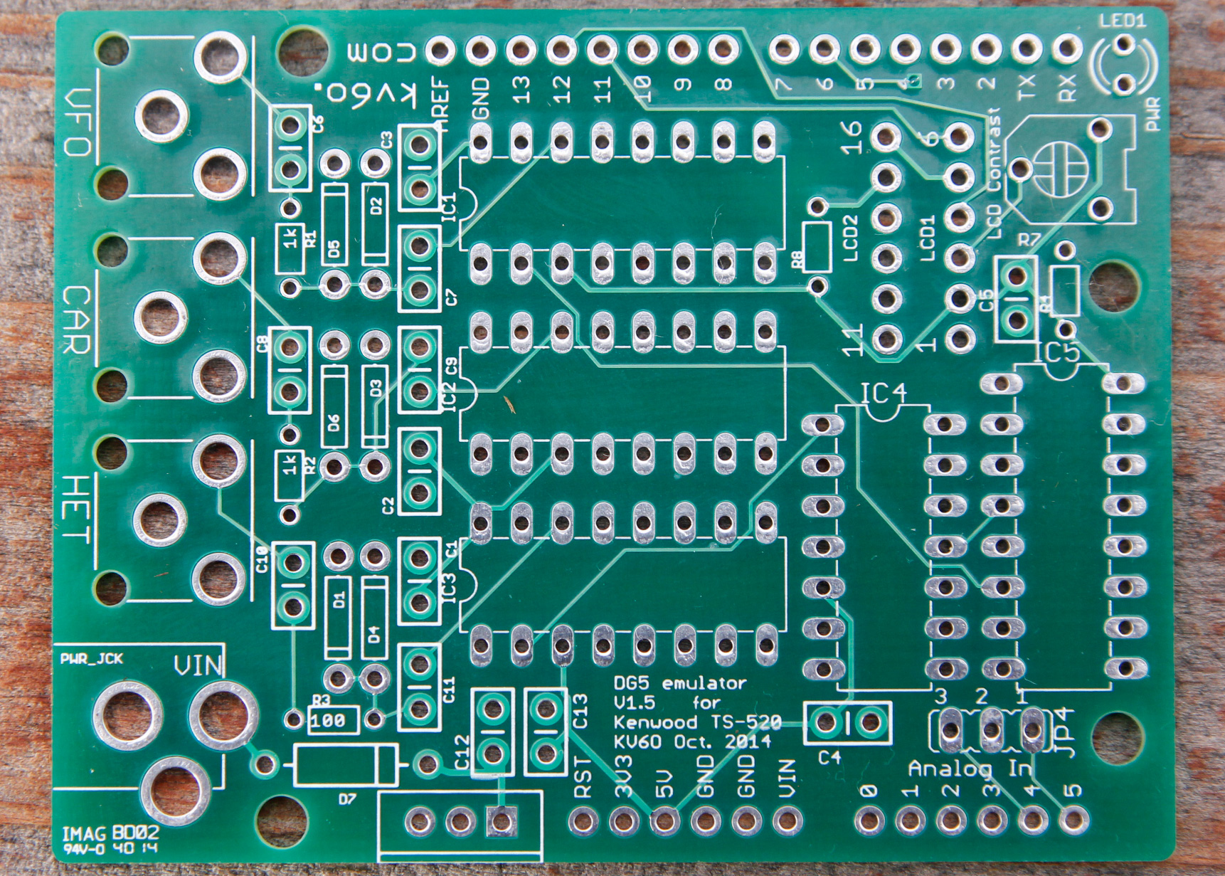
If you click on the picture of the blank PCB above, you should get a reasonably high resolution pic. You can see where R1, R2, and R3 are on the left hand side of the board.
The caps are best soldered in using the 0.1uF bypass caps (C1-C5) first, then the 0.01uF signal caps (C6-C11), just to keep the different values straight. C12 and C13 (both 0.1uF) are optional – only needed if you’re planning on using the 7805 voltage regulator (more on that below).
R4 is for the power on LED, I used a 1k resistor as I didn’t need it bright, just to tell me that it was on.
R8 is for the LCD backlight. On my LCD, I just put in a jumper – it could take 5V. If you’re going to use the one from SparkFun, it uses 4.2V, so a 6.8 ohm, 1/4 watt resistor is advised, like this one (already part of the Mouser order above).
Once you have the resistors, diodes and caps soldered, next step is the 4, 16-pin DIP sockets (IC’s 1,2,3,5), and the one, 14-pin socket (IC4). Next is the LED (LED1), the LCD contrast trimmer (R7).
Now put in the progressively taller parts, like the LCD1 and LCD2 headers – both are 6-pin’s. If you got the 40-pin break away header from SparkFun, you’ll have to use cutters to cut it into 4, 6- pin sections – 2 go in the PCB, and the other 2 go on the LCD in positions 1-6, and 11-16. (be sure you solder the connectors on the BACK of the LCD so the jumper cables connect to the BACK of the LCD, and not the front. It will work either way, but you’ll have difficulty mounting it in a box if the wire come out the front!) The 4″ jumper cables will connect these two – follow the pin labeling on the PCB to make sure that connections 1-6 go to pins 1-6 on the LCD, same for pins 11-16.
Lastly, solder in the shield headers, and the RCA connectors.
At this point I connected the 5V and GND pins to my bench power supply to make sure there was little current draw – the LED should be the only thing on. Insert the IC’s and do the same thing – the current draw should be around 20mA for the chips and the LED (assuming you used a 1k dropping resistor). We’re just checking that we don’t have a short at this stage, if your bench power supply trips in an over current or limited condition, check your soldering – there’s a short somewhere.
A note on the 7805 and it’s associated components. You can put these in if you wish, I added them as my prototype drew about 200mA. I believe this is because in the prototype I was using a black on green display (like the one from SparkFun) that draws about 120mA. The LCD I am using in this build is a white on black display, and the backlight seems to draw only 20mA or so, for a total power budget of about 65ma.
The 7805 is a linear regulator, so all the power dissapated is rejected as heat. In this case, the input voltage is about 14V (the output from the back of my TS-520S), so almost 2/3’s of the power used will be converted to heat by the regulator (since it is dropping from 14V to 5V). 9V at 200mA is 1.8W of heat being dissipated by the regulator – too much for the SMD regulator on the Arduino. I added this 7805 so an external heat sink could be used if necessary.
If you use a lower power LCD backlight, you might be able to get away with using the regulator on the Arduino. Or, if you leave it plugged into your computers USB port, it can be powered that way.
Parts Placement – click on the pic below for a higher resolution pic:
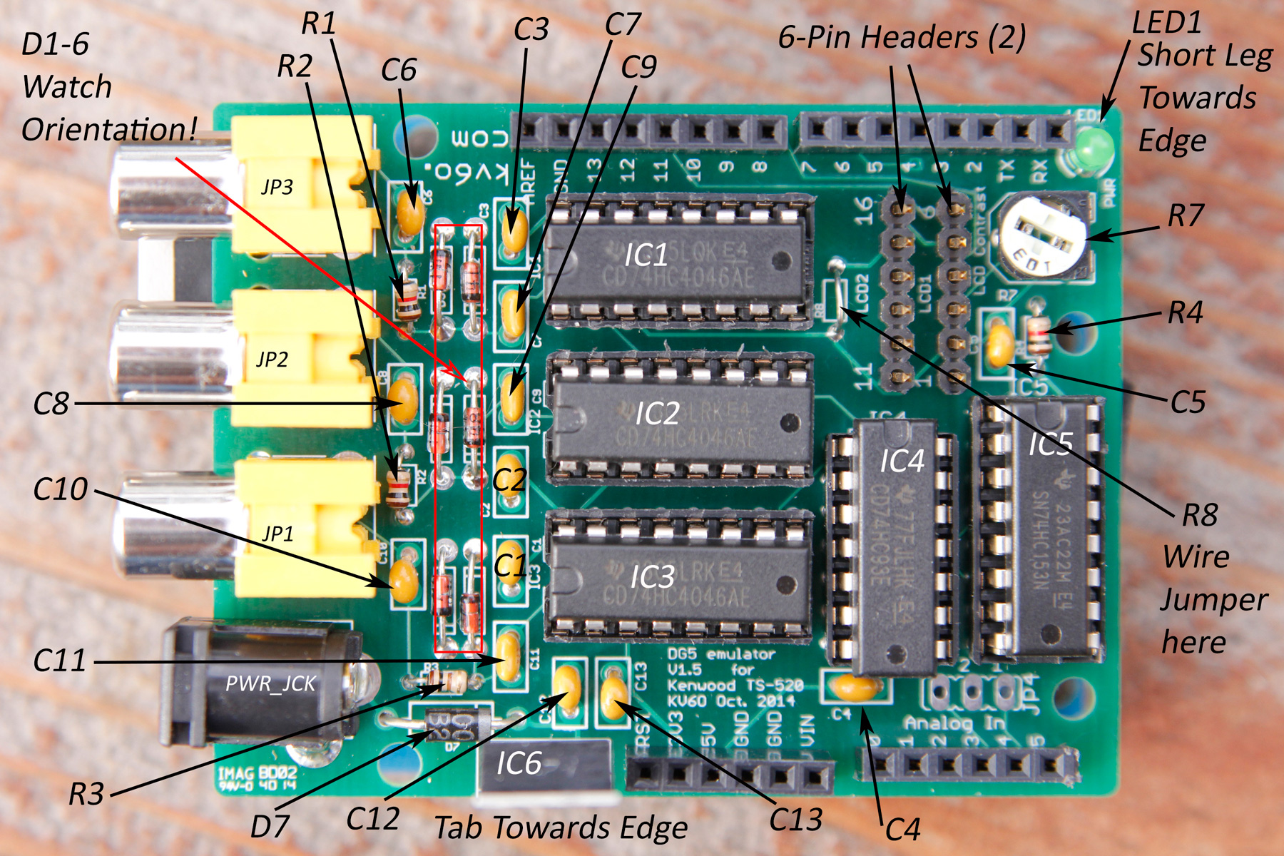
Note – R8 (the LCD backlight resistor) in my version has a jumper because a dropping resistor is included on my LCD display. The LCD in the BoM is from SparkFun, and that LCD requires a 6.8 Ohm dropping resistor (also included in the BoM).
Final notes.
At this point the shield should be ready. I trimmed the RCA tabs on the underside to help with clearance issues between the USB port on the Arduino and the RCA connectors. I also added a piece of black electrical tape to the top of the USB port to prevent shorting. The same is true for the ICSP port on the other side of the board – put a piec of electrical tape or similar on the underside of the shield to prevent the pins from shorting. This is a comon issue with Arduino shields, and the busier the board, the more this is an issue – and this board is packed!
Connect the board to the LCD display (pay attention to the pin numbers!), connect the shield to the radio using a set of audio/video cables, load up the Arduino with the code and you’re in business!
I’d love to hear from folks who have built this – with or without my PCB – please leave a post!
Steve
4/8/17 – Eagle, INO and BoM files have been moved to Github. LCD, LED and Nixie code is available.
See the main page for updates to this project I have posted over time: https://www.kv6o.com/wordpress/
Click the “Buy Now” button below to order a DG5 Emulator (In stock as of 10/20/19):
BEFORE BUYING PLEASE NOTE: (2/8/2020): The Arduino Duemilanove is difficult to find, and the 3 RCA connectors used in this design are no longer available. If you have a Duemilanove, and can solder jumpers to panel mount RCA connectors, you should have no problems. I am working on a new PCB that will address both these issues, but it’s not available yet.
STOCK UPDATE – 10/20/19 – New run of PCB’s in stock.
STOCK UPDATE – 9/17/19 – Out of stock at this point. I have shipped several hundred boards all over the world at this point, but orders have slowed down to the point that I am not sure it’s worth making another run.
STOCK UPDATE – 4/17/16 – new boards are in stock, same price. Shipping might have to be adjusted, the last few I shipped cost more than I was charging due to some USPS shipping changes early in the year, we’ll see as these orders come in as I know the First Class postage actually dropped recently.
Boards are $8 each, plus $2.50 shipping to the US only, no matter how many you buy. 1 board is $10.50 shipped, 2 would be $18.50. For International shipping, see note above “Buy Now” button.
Thanks!
Steve, KV6O