Author Archives: admin

New boards should be here any day, build pics from Mike, KD2DYY

To all those who have e-mailed me about boards, I should have the new run here soon, maybe even today! (UPDATE – FedEx says Tuesday, 12/2)  I’ll send each who requested an e-mail when I have them in hand.

Mike, KD2DYY sent me some pics of his build – nice work!  He did have some issues with the version of code, and the cable sets he was using – make sure you’re using the latest code (V1.5) that can be found on the build page:

Also, do make sure that the RCA cables you are using are good – I am using a set of cables that were from an old AV piece of gear. It’s original use was to carry Left and Right audio, and composite video, and it seems to work fine in this application.  Mike had to try 3 different cable sets before he got it working.  Here are some pics of his build:

DSC02666


DSC02669

Nice work, Mike!


DG5 Emulator Boards stock status

UPDATE 11/17/14 – new run of boards have been ordered today from AccuTrace, with a scheduled ship date (to me) of 11/24/14.  Rather than accepting orders right now, I’ll ship first come, first served to those who express interest via a post here.  No commitment, but if your interested please post a reply to this post (below) and I’ll reach out to you first.  After those orders have been fulfilled, I’ll reactivate the “buy now” link on the project page.  Thanks!

UPDATE – SOLD OUT as of 11/13/14. Please post here if you’re interested in a board – I’ll make more if folks want them!

I only have one more board (my original order was for 20), when that one is sold, the PayPal button should direct folks who want to buy a board here.  If you’re interested in a PCB for this project, please leave me a note – if there’s enough interest I’ll have another run of boards made an e-mail you when they come in.

Steve

ToddFun.com build video

Todd over at www.toddfun.com has posted a new video, part 5 in his Arduino Frequency Display For Kenwood TS-520S HF Ham Radio series:

http://www.toddfun.com/2014/11/02/arduino-frequency-display-for-kenwood-ts-520s-hf-ham-radio-part-5/

In the video, he solders up the project, mounts it in a chassis, and tests it out.  You can also see the previous 4 parts on how he came up with the design on his website.  Nice to see it built and working out side of my bench!

They did have an issue with the frequency appearing to be slightly off, that might have been the version of code he was running – the gate time seems to work best (and be most accurate) at 125mS, the original code was using 100mS.  Another issue that I have run into is that the later Arduino’s (like the UNO) do NOT use a crystal for the clock – they use a ceramic resonator.  Fine if you want to blink some LED’s, not so good if you want to measure a frequency.  Todd and I both used Arduino  Duemilanove’s – they can still be purchased at places like Amazon.com.

This is all open source – you can download the project, the BOM and the code from this page.

Great to see the end product. Let me know if you build one!

Steve

DG5 mounted and ready to go!

I ordered up a 2″x4″x 5″ extruded aluminum chassis off of eBay, and mounted the DG5 and the LCD display.

DG5_in_case_front

DG5_in_case_back

It’s looks good, and the metal shielding eliminated some slight RFI from the board.  There are multiple, HF signals on the board being amplified and switched – a metal chassis is recommended!

DG5withTS-520

Looks good on top of the TS-520S!

Strange dreams about VFO drift.

I have strange dreams.  I often awake with new ideas on something that I am working on, which really isn’t all that strange, but when I try to explain my dreams to my wife, well…. they’re strange.

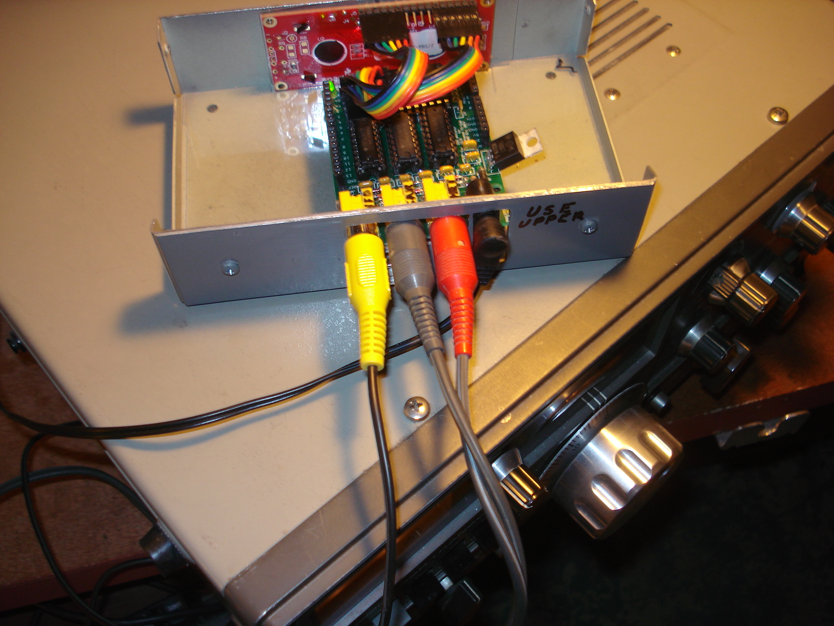
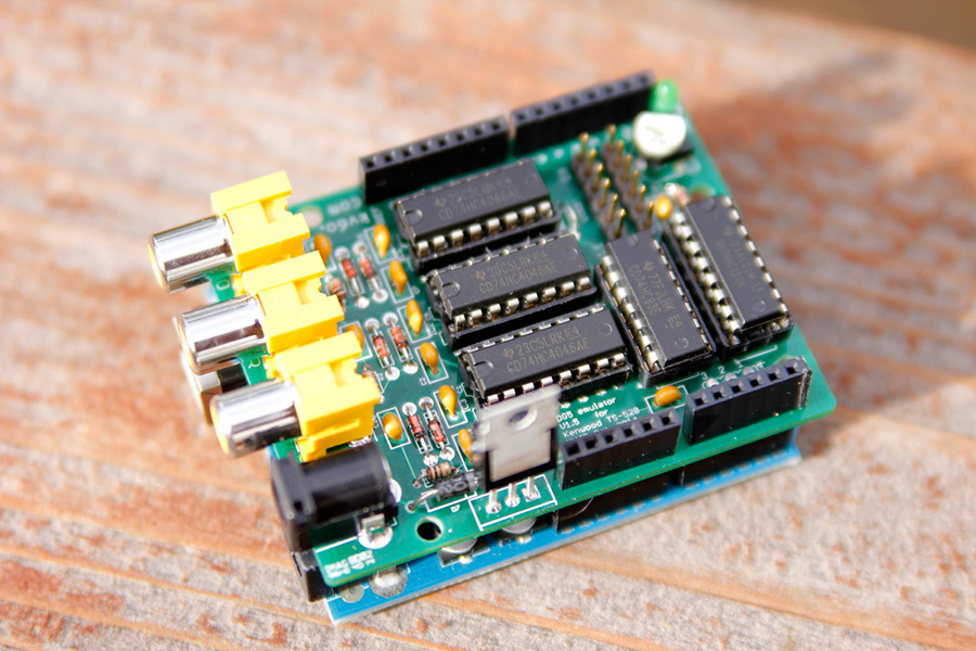
Yesterday morning I woke up thinking about other things I could do with the DG5 shield, and one of the things I dreamed about was making VFO drift measurements.  Using the DG5 emulator and the USB communications with the computer, I could log the calculated VFO frequency over time, and see how my VFO drifted during warmup.  This was pretty straight forward, instead of scanning thru three frequencies to measure, I just locked the board to the VFO and increased the gate time to 1 second, and took a measurement every 6 seconds.  I printed these results to the serial port and captured them with my computer.

Now, there’s another source of drift in this setup, and that’s the crystal oscillator on the Arduino itself.  The crystal’s I have used for other ATMega328 based project boards are rated at 20ppm at 16Mhz – the clock frequency the Arduino uses. 20ppm works out to be +/- 320 Hz = quite a bit of potential measurement error!  But crystals don’t usually drift all over the place in short periods of time, with relativity stable temperatures.  I had the Arduino and the shield powered up overnight with the TS-520S off, so I figured it would be pretty stable for a measurement of the TS-520S VFO drift during warm-up.

Uncorrected-VFO-drift-at-warmup

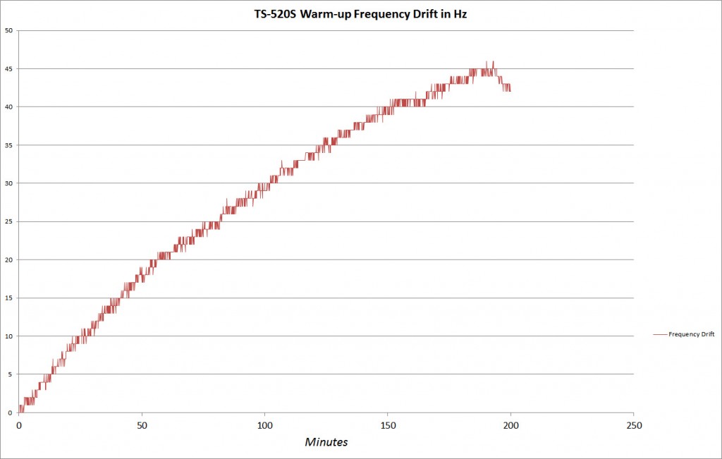
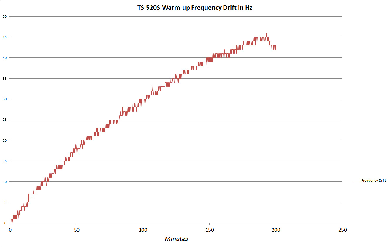
Here’s the drift plot over about 3 hours of warmup.  I suspect most of the calculated drift is the TS-520S VFO, and not the Arduino. But we can actually eliminate the Arduino’s error using one of the DG5’s other inputs.

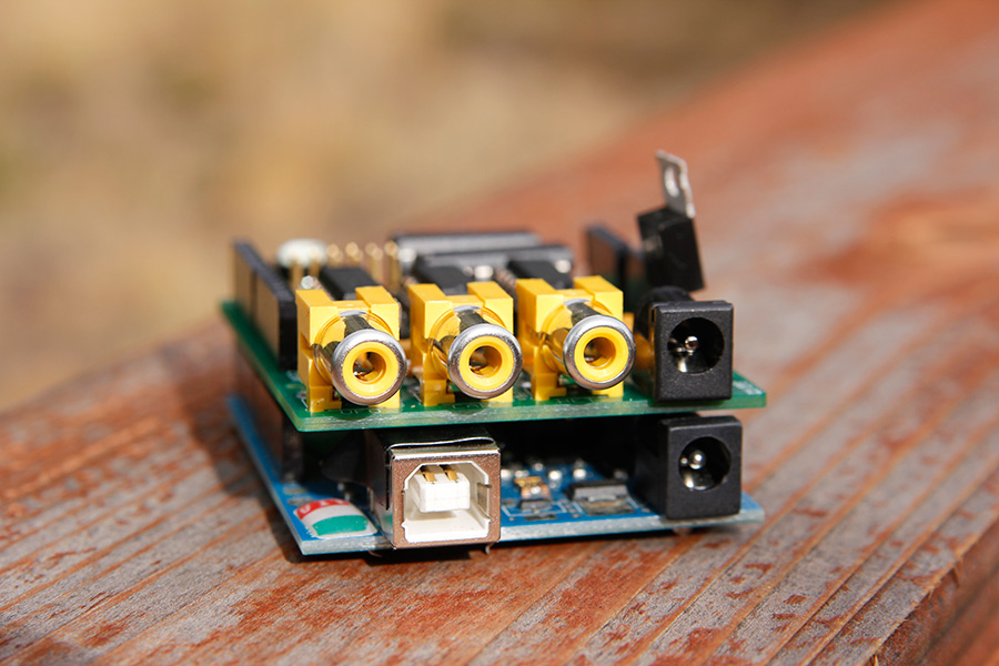
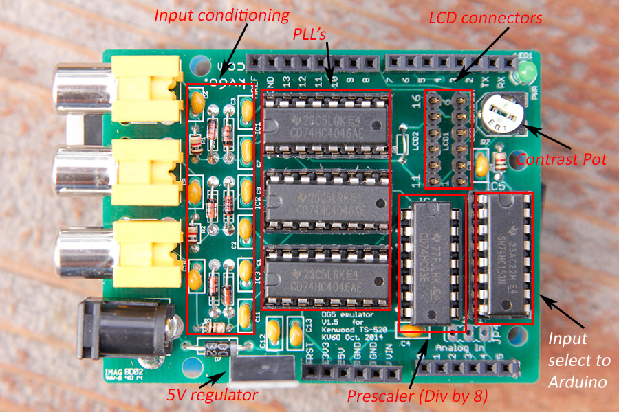
By using an external frequency reference, we can eliminate the Arduino as a source of the error.  The DG5 emulater can select from 3 inputs for measuring (2 direct, 1 prescaled by a divide by 8 counter), so I used my HP 8924C as an external frequency reference. It uses an OCXO (Oven Controlled Crystal Oscillator) for it’s frequency source, which is much better than the $0.39 Arduino crystal. I don’t have the spec’s in front of me, but if I remember correctly, it’s something like 0.05 ppm or better.  I have used it to obtain sub 1 Hz measurements in the ARRL Frequency Measurement Test (http://www.b4h.net/fmt/fmtresults201404.php), so it’s pretty good at these frequencies.

This time I had the program select the VFO input, make a measurement, then select the external frequency reference (which was set to 5.000000 Mhz) , and make another measurement, Since we know the input frequency is 5.000000 Mhz we can calculate the error, then apply that error to the measured VFO frequency.  The data of the Arduino looks like this:

VFO,REF,ERROR,FREQUENCY,Millis
5000064,4999944,-56,5000008,10043
5000064,4999945,-55,5000009,15044
5000064,4999944,-56,5000008,20045
5000064,4999945,-55,5000009,25046
5000064,4999944,-56,5000008,30047
5000065,4999945,-55,5000010,35048
5000064,4999945,-55,5000009,40049
5000064,4999945,-55,5000009,45050
5000064,4999944,-56,5000008,50051
5000064,4999945,-55,5000009,55052
5000064,4999944,-56,5000008,60053
5000064,4999945,-55,5000009,65054

That’s the fist minute or so of data out of the Arduino.  The columns are VFO (the raw measured frequency), the Ref (the 5 Mhz reference frequency as measured by the Arduino), The calculated error (REF – 5,000,000), the corrected VFO frequency (Measured VFO + ERROR), and lastly the millis() function out of the Arduino which gives us the Millis counter value – how many milliseconds we’ve been running.

Put this in to Excel, and we get this:

Arduino-Measurement-Error

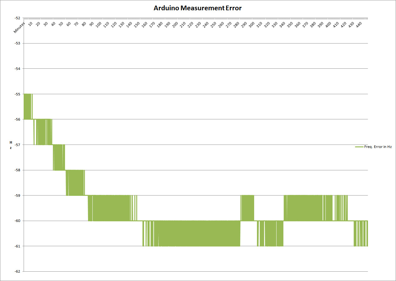
Here’s the calculated error in Hz over about 7 1/2 hours (I left it running overnight).  Looks like the Arduino is -59.512 Hz low on average, but drifted only about 5Hz during the test.  Not bad, and perhaps I should add a frequency error compensation factor in the DG5 code.

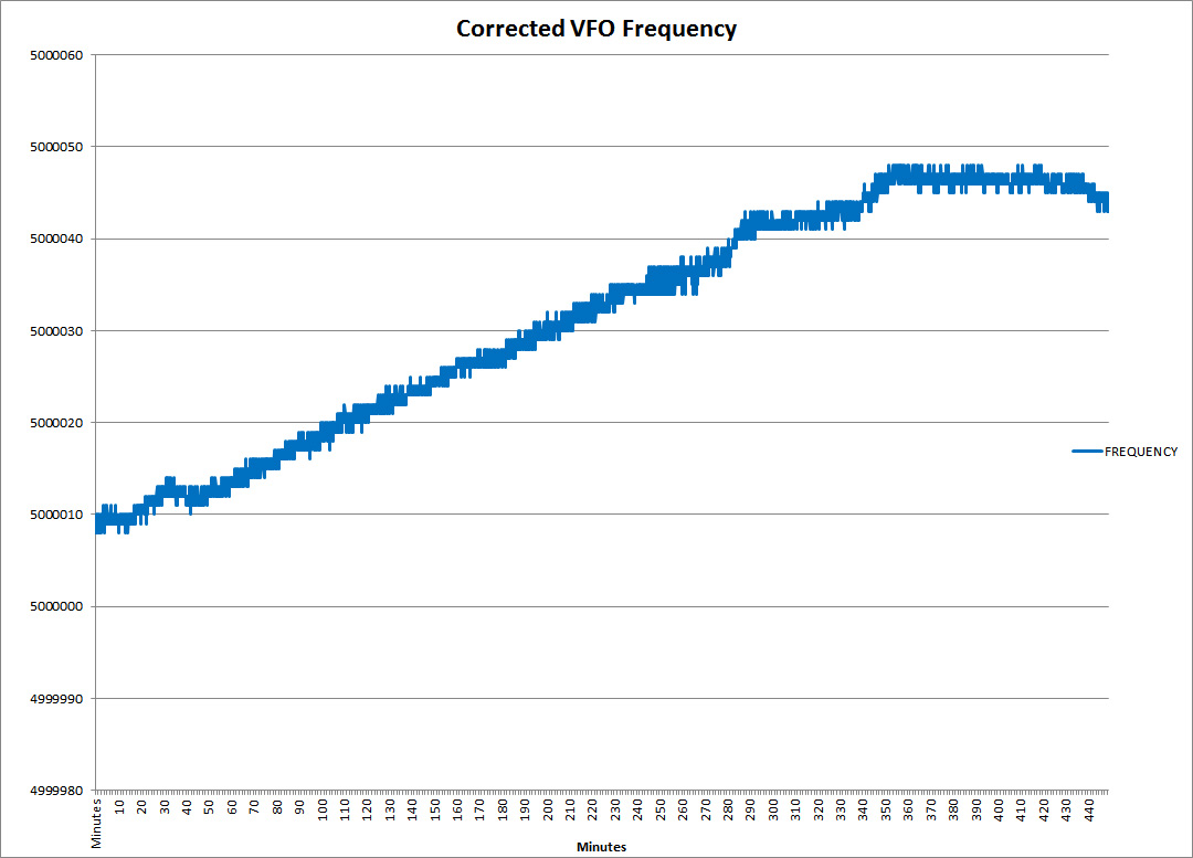
Here’s the corrected VFO drift over 7 1/2 hours:

CorrectedVFOfrequencydrift


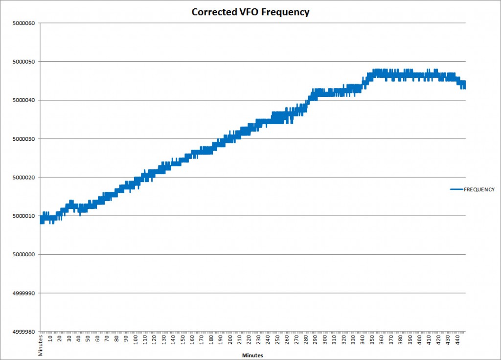
Even after running all day, the TS-520S’s VFO continues to drift appreciably – about 40Hz over this time frame.  No big deal – it’s amazingly stable for the technology – but it’s sure nice to be able to characterize it!

Points learned:

  • It looks like the Arduino frequency stability is about 10x better than the TS-520’s VFO in this setup, which is good since we’re looking to the Arduino to measure the VFO.
  • I have only measured the VFO so far, I’ll probably do a similar exercise with the BFO (which mixes with the VFO to obtain the IF frequency) and the Hetrodyne oscillator (HET) to see how stable they are.

The DG5 shield can be a useful tool as well as a frequency display!

Steve

DG5 Emulator Version 1.5 PCB’s have arrived!

Got the boards in yesterday, was feeling pretty confident about the design, so I ordered 20 this time.  Lucky, the boards look good, and the first one I built fired up right away – whew!

_MG_8852_web

Here it’s fully populated and mounted on an Arduino Duemilanove.

_MG_8862


The new boards are a bit more packed than version 1 as they have a few more features.  There’s a 5V 7805 regulator option, 2, 6-pin headers for an external LCD (with a contrast pot), and 4 mounting holes that match up to the Arduino boards.  Quality looks good, these are from Accutrace here in the US – see www.pcb4u.com for info.  Only 2 weeks as opposed to 4 or so from China.

_MG_8853


_MG_8854


With the boards packed, the clearances between the Arduino and the DG5 shield are tight – too tight in areas as is a usual issue with shields.  I put a piece of electrical tape over the top of the USB connector, and trimmed the mounting tabs for the RCA connectors that protruded thru a little too far.  I also covered the ICSP connector to keep it from touching.

Blocks

Here’s the layout.

_MG_8858_web


The 6 pin jumper cables I had are a little long, 12″ I think.  I’ll be ordering up some 4″ jumpers that will make it easy to mount in a case.

If you’re interested in a board, leave me a note here and I’ll get in touch with you!  I am working on the Bill of Materials for the complete kit – I had a lot of parts in my parts bin so I haven’t sourced everything, but most parts are available from Mouser, and a couple are from SparkFun (RCA connectors, LCD Jumpers, shield headers).

A DDS VFO for the TS-520S

While I am waiting for the new DG5 boards to arrive (they shipped yesterday – yay!), I decided to see if I could get the AD9850 DDS module I got on eBay to work as an external VFO.  If you search “DDS AD9850” on eBay you should find lots.

This is mine.

IMG_20141010_202053361_web

The module is being controlled with an Arduino UNO – it sends the desired frequency serially to the DDS chip.  The Arduino is also attached to a rotary encoder for frequency input, as well as an LCD display.  In this prototype, the LCD display is showing the DDS frequency, not the VFO frequency.  I don’t really need a display on the VFO since the DG5 emulator already displays the dial frequency.  An additional advantage to this is I don’t have to worry about the radio Carrier/BFO and Heterodyne oscillators warm-up drift as the dial frequency is being calculated using these actual frequencies by the DG5 emulator.

I put a 0.01uF cap between the output of the DDS and the VFO signal input on the TS-520 to block any DC component present on the output from the module.   The stock output was a little low, but worked – signals were a bit low- 3-4 S units as compared to my K3.  Looking at the datasheet for the DDS module, there is a 3.9k ohm resistor called “Rset”, which sets the DAC’s full scale output current.  I put a 2.2k resistor in parallel with it (just soldered it on top of the existing 3.9k SMD part, you can see it in the pic above) to lower the Rset value and increase the DAC output – bingo!  Signals are on par with the K3, and signal reports are good.  I’ll need to make sure I am not saturating the output or causing any distortion – I might need a buffer amplifier if there are any problems. Looked OK on the scope.


Next steps will be to get it in a case on a protoboard, and establish communications between the DG5 emulator and the VFO – the DG5 is connected to the computer, and I can have the computer tell the DDS what frequency to go to, and I might be able to use one display.  At this point I am leaning to independent boxes as the DG5 box is best on top of the TS-520, and the VFO would be best off to the side with the VFO knob and at the same general height as the existing VFO knob.  The rotary encoder I am using is a cheap mechanical type with detents, I’ll need to get a higher resolution, smoother encoder (probably optical) for the final design.

Let me know what you think!

Steve – KV6O

P.S. – I have been in touch with Todd at ToddFun, I sent him a couple of the first run PCB’s for the DG5 emulator – he’s building it and will be posting a new video with the DG5 emulator soon!  Keep your eye out for it!

DG5 emulator version 1.4 ready to go!

I finished up on the changes and tweaks I wanted to make to the design, new schematic below.  I think I have found a US based PCB house (in Nor Cal, no less!) that can do a run for not much more that what I would pay for the China based house I used last time.  I should have the boards in less than 2 weeks as opposed to close to 4 weeks.  Since I just finished it up today, and it’s Friday, I’ll wait till Monday to submit the design, giving me 2 days to look it over for any problems.

EagleV1_4

Few things I addressed in this version:

  • Rotated the board on the shield so the inputs are on the same side as the Arduino USB port.
  • Fixed 3 wiring errors.
  • Added headers for attaching an LCD display with contrast potentiometer and optional dropping resistor for LED back-light. This will use 2, 6 pin jumpers to connect to the LCD.
  • Corrected some of the cap and resistor solder pads, should be easier to solder.
  • Fixed silkscreen errors on shield headers.
  • Added optional 7805 regulator and 2.1mm power jack for running standalone (no USB power). 7805 WILL need heatsink as it’s dissipating around 2W, almost twice what the board, LCD and Arduino uses since it’s dropping 14V (from the back of the TS-520) down to 5V.

I looked at using a triple gang RCA jack, but couldn’t find one with an Eagle footprint, so I am sticking with the single jacks from Sparkfun for now. There is too much risk designing the footprint off the datasheet, part unseen.

Download (PDF, 34KB)

New schematic.  Only difference from the one below should be the addition of the 7805 and supporting components.

DG5 emulator Version 1 PCB’s have arrived

Yippie!  The boards arrived last week and it was a few day’s before I could get to them.  They sure looked nice!

DG5_V1_unpopulated_top

I was working on version 1.1 of the layout before these boards even arrived as I realized that the inputs for the VFO/CAR/HET were on the opposite side of the board from the USB connector – not convenient if you want to mount the assembly in a chassis.  But I was anxious to get this first version up and running to see if I got the schematic correct in Eagle.  And as is usual, I found a couple of minor problems.

DG5_V1_populated_bottom

Here’s a view of the bottom of the populated board – note the 3 jumpers. Turns out I made a few mistakes – one was bringing a NET on the Eagle schematic over the pin and near the chip – missing the intended connection to the pin.  Another one was missing an air wire – a ground “island” was created without a connection to ground.  And lastly, I wired to the wrong output pin on the 74LS93 counter, winding up dividing by 4 rather than 8.  All three errors were corrected with jumpers.

There is also some silkscreen mistakes, I somehow incorrectly labeled the Arduino shield pins in two areas – not critical.

DG5_V1_populated_top

Here’s the board fully populated from the top.

Few other issues with this version that I have corrected with version 1.1:

  • Some of the Eagle parts used solder pads that are pretty small, making soldering a little more difficult.
  • I had 2 LED’s for showing which input was selected on the LS74153, which I have removed in version 1.1 to save board space, they weren’t really necessary.

As I work on the new version in Eagle, I am trying to keep in mind a few other things now that I have an actual, working shield.

  • Arduino to shield clearance – putting the RCA connectors on the same side as the USB connector makes it easy to short things out.  A little bit of electrical tape on top of the USB connector should prevent this.
  • Need to keep the PLL output signals as short as possible as they are 5V TTL level representations of the original, low level signals – a potential RFI issue.  Using the shield design this isn’t really possible as the signal exits the shield to the main Arduino board on Pin 5.  A better design would put everything on one PCB, keeping HF signals nets as short as possible. Another way of reducing this issue as a good, shielded enclosure.
  • Might need to add an LM7805 so it can run without being connected to the computer via USB.  I added one to my original prototype since it has an LCD display and isn’t dependent on a computer.  The LCD’s backlight and the Arduino draw enough current that a good heat sink is required to drop the 13.8VDC (provided at the back of the TS-520 for the DG5) to 5VDC.

Arduino’s with shields don’t lend themselves well to enclosures, so one possibility might be to make a larger shield that an Arduino plugs into that can slide into an extruded aluminum enclosure.  The Arduino would be a “daughter card” in this scenario, plugged in up side down on the main board.

My TS-520 still uses the prototype shown below since it’s already mounted in an enclosure and has the LCD display added, which was something I added after I sent in the version 1.0 PCB design.

Download (PDF, 31KB)

My current schematic, with 2, 6-pin jumpers to go to a 16-pin LCD display (only the first 6, and last 6 pins are used on the display).

Latest Arduino code with LCD support (note the pins used for the LCD):

[wpdm_file id=3]

Note – I have only tested this with the Arduino UNO and Duemilanove boards.  There are probably issues with other Arduino boards, such as the Leonardo, as they use the internal TIMERs for USB emulation.

If you’re interested in the eagle files, drop me a line.